
User Manual


3UG4621/3UG4622 current monitoring relays
7.6 Circuit diagrams
3UG4 / 3RR2 monitoring relays
162 Manual, 02/2013, NEB927043002000/RS-AA/002
7.6 Circuit diagrams
7.6.1 Internal circuit diagrams
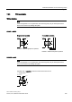
Internal circuit diagrams 3UG4621 / 3UG4622
$
0
,!
,1
$
Figure 7-1 3UG4621/3UG4622 current monitoring relays
Note
On the 24 V AC / DC version of the 3UG4621/22-.AA30, terminals A2 and M (GND) are
electrically connected in the device! The load current must flow through terminal M (GND).
On the 24 to 240 V AC/DC versions of the 3UG4621/22-.AW30, terminals A2 and M (GND)
are electrically separated!