
User Manual


3UG4621/3UG4622 current monitoring relays
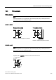
7.6 Circuit diagrams
3UG4 / 3RR2 monitoring relays
164 Manual, 02/2013, NEB927043002000/RS-AA/002
• three-phase
load
24 V AC/DC
< >
A1
IN
L3 L2 L1
M
A2
o.k.
< >
A2
A1
o.k.
M
L1 L2 L3
IN
24 V AC/DC
load
Operation with a common control circuit and load current circuit
• single-phase
< >
A2 M
A1
IN
< >
11
1412
A2 M
A1 IN
24 V AC/DC
24 V AC/DC
Load
Load
optional
o.k.o.k.
Note
Configuration
In the case of 3UG462.-.AA30, A2 and M (GND) are internally electrically connected!
If the load to be monitored and the current monitoring relay are powered from the same
system, terminal A2 is not required!
The load current must always flow away through M (GND), otherwise the current monitoring
relay may be destroyed!