
User Manual


3UG4625 residual current monitoring relay with 3UL23 transformer
9.6 Circuit diagrams
3UG4 / 3RR2 monitoring relays
Manual, 02/2013, NEB927043002000/RS-AA/002
199
9.6 Circuit diagrams
9.6.1 Internal circuit diagrams
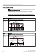
3UG4625 internal circuit diagrams
&&
$
$
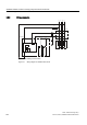
Figure 9-1 3UG4625-.CW30 residual current monitoring relay, 24 to 240 V
Note
3UG4625 residual current monitoring relays are suitable for operation with 3UL23 residual
current transformers for external ground-fault monitoring. The output signal of the
3UL23 residual current transformer is connected to terminals C1 and C2 of the monitoring
relay. To avoid interference injection, which could result in incorrect measurements, these
connecting lines must be routed as parallel as possible and twisted, or shielded cables must
be used.