
Service manual


REC 3829 4-16
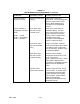
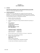
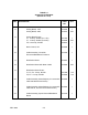
TABLE 4-2
POWER TROUBLESHOOTING PROCEDURE
ACTION CORRECTIVE ACTION
Measure DC Voltages at Analog
Board Test Points TP2 and TP3,
loadcell excitation voltage at TB3-
1,2 and +12V at TB4-2. Use test
connector J13-6 as common.
If all DC Voltages are OK, perform board
troubleshooting procedures, refer to Table
4-1.
If all DC Voltages are at or near zero, check
AC Voltages.
If any one or more of DC Voltages are low or
zero, isolate fault to the Analog Board or field
wiring.
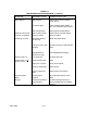
Check AC Voltages at transformer
connector J3:
J3-1 HOT - L1
J3-4 NEUTRAL - L2
If no AC Voltage, check fuses F4 and F5 on
Distribution Board, and F1 and F2 on the
Analog Board. Refer to Distribution Board
and Analog Board Replacement Procedures
in this chapter for fuse location and value.
If fuse F4 and F5 are OK, problem exists with
main AC input power. Check external power
source.
If fuse F4 or F5 on Distribution Board or fuse
F1 or F2 on Analog Board are blown, replace
fuse and restore power.
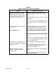
Isolate fault to single board; remove
AC power, unplug the CPU Board.
Reapply AC power
If DC Voltage is OK, replace CPU Board.
If DC Voltage is not OK, plug in CPU Board
and check the Display and optional
Communication Boards.
Remove AC power. Unplug
optional Communication Board.
Reapply power.
If DC voltage is OK, replace Communication
Board.
If not OK, insert Communication Board and
check Display Module.