
Service manual


REC 3829 6-12
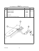
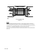
EIA-232 CONNECTIONS
FIGURE 6-2
EIA-232
Typical connections are shown in Figure 6-2. In some cases, wires may need to be
swapped (null modem connections). This is done by swapping wires 2-3, 4-5, and 6-20.
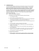
To make the Comm Loop Back test pass, connect a jumper wire between pins 2 and 3 of
connector P2. If hardware handshaking is used, also connect pins 4-5.
If your device cannot drive the RTS line, insure the DIP switches are set to EIA-232 data
leads only.