SpeedStream® Router User’s Guide Series 4100 and 4200 Part No.
© Copyright 2004, Siemens Subscriber Network. All rights reserved. Printed in the U.S.A. Product names mentioned herein may be trademarks and/or registered trademarks of their respective companies. Siemens Subscriber Networks shall not be liable for technical or editorial errors or omissions in this document; nor for incidental or consequential damages resulting from the furnishing, performance, or use of this material.
SSN will not honor, and will consider the warranty voided, if: (1) the seal or serial number on the Product have been tampered with; (2) the Product’s case has been opened; or (3) there has been any attempted or actual repair or modification of the Product by anyone other than an SSN authorized service provider. The limited warranty does not cover defects in appearance, cosmetic, decorative or structural items, including framing, and any non-operative parts.
Router User’s Guide Contents INTRODUCTION........................................................................................................................................... 3 Features of the SpeedStream® Router............................................................................................... 3 Network (LAN) Features .................................................................................................................. 3 Security Features......................................
Router User’s Guide Contents Dynamic DNS ................................................................................................................................ 37 CONFIGURING SECURITY FEATURES................................................................................................... 38 Admin User .................................................................................................................................... 39 Time Client...............................................
Router User’s Guide 1 Chapter 1 Introduction Congratulations on the purchase of the SpeedStream® Router with SecureRouteTM SpeedStream® Router (Router) is a powerful yet simple communication device for connecting your computer or local area network (LAN) to the Internet. This manual covers the SpeedStream model series 4100 and 4200.
Router User’s Guide Introduction • Virtual Private Network Virtual Private Network allows remote users to establish a secure connection to a corporate network by setting pass-through of the three most commonly used VPN protocols: PPTP, L2TP, and IPSec. Configuration & Management • Easy Setup Use your Web browser for quick and easy configuration. • UPnP Support Universal Plug and Play (UPnP) allows automatic discovery and configuration of the SpeedStream Router.
Residential Gateway Family User Guide 2 Chapter 2 Physical Installation This chapter covers the physical installation of the SpeedStream Router. Minimum System Requirements • DSL service and an Internet access account from an Internet Service Provider (ISP). • Network cables for the device you intend to connect to the Router. Use standard CAT5 Ethernet cables with RJ45 connectors. • TCP/IP network protocol must be installed on all computers.
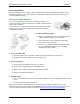
Residential Gateway Family User Guide Installation Installing Line Filters Because DSL shares your telephone line, you may need to separate the two signals so they do not interfere with each other. A line filter (may be included with some models) prevents DSL traffic from disrupting the voice signal on the telephone line, and vice versa. Follow the procedures below to install line filters on any device (telephones, fax machines, caller ID boxes) that shares the same telephone line with your DSL.
Residential Gateway Family User Guide Installation Connecting Cables The Router provides ports for either a USB or an Ethernet connection to your primary computer. Select the interface you will use to connect the Router, and follow the step-by-step instructions below for your chosen installation method. Ethernet Installation Method To connect the SpeedStream Router via the Ethernet interface, your computer must have an Ethernet adapter (also called a network interface card, or “NIC”) installed.
Residential Gateway Family User Guide Installation USB Installation Method (Microsoft Windows) 1. Connect the USB Cable 1) With your computer off, connect the provided USB cable to the USB port on the Router. 2) Connect the other end of the USB cable to an open USB port on your computer. 3) If desired, use standard 10/100 CAT5 Ethernet cables to connect additional computers to the Ethernet ports on the Router. 2.
Router User’s Guide Chapter 3 Operating System Configuration This chapter explains how to configure your computer to work with the Router. To access the Internet through the SpeedStream Router, the TCP/IP protocol must be installed on your computer. If TCP/IP is not already installed on your computer, refer to your system documentation or online help for instructions. Once installed, you should check the TCP/IP protocol settings to make sure they are correct for use with the Router.
Router User’s Guide Operating System Configuration Checking TCP/IP Settings (Windows 9x/ME) 1. Select Start>Control Panel >Network. This displays the Configuration tab on the “Network” window. 2. Select the TCP/IP protocol for your network card. 3. Click Properties. This displays the “TCP/IP Properties” window. 4. Click the IP Address tab. 5. Ensure that the Obtain an IP address automatically option is selected. This is the default Windows settings. 6. Close this window. 7.
Router User’s Guide Operating System Configuration Checking TCP/IP Settings (Windows 2000) 1. On the Windows taskbar click Start>Settings>Control Panel. This displays the “Control Panel” window. 2. Double-click Network and Dial-up Connections. This displays the “Network and Dial-up Connections” window. 3. Right-click Local Area Connection and select Properties. This displays the “Local Area Connections Properties” window. 4. Select the TCP/IP protocol for your network card. 5. Click Properties.
Router User’s Guide Operating System Configuration Checking TCP/IP Settings (Windows XP) 1. On the Windows taskbar click Start>Control Panel. This displays the “Control Panel” window. 2. Double-click the Network Connection icon. This displays the “Network Connections” window. 3. Right-click Local Area Connection, then click Properties. This displays the “Local Area Connection Properties” window. 4. Select the TCP/IP protocol for your network card. 5. Click Properties.
Router User’s Guide Operating System Configuration Checking TCP/IP Settings (MAC OS 8.6 through 9.x) 1. Select Apple >Control Panel >TCP/IP. This displays the “TCP/IP” window. 2. Select one of the following from the Connect via drop-down menu. • Ethernet or Ethernet built-in if connecting via Ethernet. • Ethernet Adaptor [en0,en1,…] if connecting via USB. 3. Select Using DHCP Server from the Configure drop-down menu. 4. Close the “TCP/IP window” and click Save. 5. Reboot when configuration is saved.
Router User’s Guide Operating System Configuration Checking TCP/IP Settings (MAC OSX) 1. Click Apple -> System Preferences. This displays the “System Preferences” window. 2. Double-click the Network icon under the Internet & Network section. This displays the “Network” window. 3. Select one of the following from the Show drop-down menu: • Built-in Ethernet if connecting via Ethernet. • Ethernet Adaptor [en0,en1,…] if connecting via USB. 4. Select Using DHCP Server from the Configure IPv4 drop-down menu.
Router User’s Guide Operating System Configuration Internet Access Configuration Windows users must configure their computers to use the Router for Internet access. Ensure that the Router is installed correctly and the DSL line is functional. Then follow the appropriate procedure below to configure your Web browser to access the Internet via the LAN, rather than by a dial-up connection. For Windows 9x/2000 1. Select Start>Settings>Control Panel to display the Control Panel. 2.
Router User’s Guide 4 Chapter 4 SpeedStream Router Setup This chapter provides details for the Router setup processes. This chapter describes the steps to set up the SpeedStream Router configuration using the Router Setup Wizard. Other configuration may also be required on the Router, depending on which features and functions of the SpeedStream Router you wish to use. Use the table below to locate detailed instructions for the required functions. To do this: Refer to: Configure users on the Router.
Router User’s Guide SpeedStream Router Setup Connecting to the Router The SpeedStream Router contains an HTTP server that allows you to connect to the Router and configure it from your Web browser (Microsoft Internet Explorer or Netscape Navigator, versions 5.0 or later). To establish a connection from your computer to the Router: 1. After installing the Router, start your computer. If your computer is already running, reboot it. 2. Open your Internet Explorer or Netscape Navigator Web browser. 3.
Router User’s Guide SpeedStream Router Setup • If you have multiple Point-to-Point (PPP) connections configured, the PPP Login [choose connection] screen displays the available connections. Refer to Selecting PPP Connection for more details. Point-to-Point offers the Connect on Demand feature whereby the router will attempt to log on to a disconnected PPP session if there is requested traffic from the LAN side, and if there is a saved user name and password.
Router User’s Guide SpeedStream Router Setup PPP Login If you have configured only one PPP (Point-to-Point) session on your computer, the “Login” window for that PPP connection is displayed after you log on using the “Administrative User Setup” window. 1. Front the PPP Login window, enter the Username and Password. 2. To save the settings so you won’t be asked for the user name and password in the future, click Save Settings on Connect. 3. To configure additional PPP options, click Show Options.
Router User’s Guide SpeedStream Router Setup Home Window After initial startup, the “Home” window is displayed on startup. In the left navigation pane of the “Home” window, there are configuration, diagnostic, status and statistic options for the Router. The list of options displayed differs depending on how a user is logged into the system.
Router User’s Guide Chapter 5 Configuring User Profiles 5 This chapter contains details for configuring users on the SpeedStream Router. User profiles are used as a means for controlling Router and network access by individual users. Access to the configuration and management of the Router should be restricted to authorized users only. This chapter describes how to: • Add user profiles • Edit user profiles • Delete User Profiles Add User Profiles To add a new user profile: 1.
Router User’s Guide Configuring Use Profiles 6. Click Next. This displays the “Profile Content Filtering” window. Content filtering restricts access to undesirable Web sites and Web content. 7. Select one of the following content filtering options: • Disable all Content Filtering User has access to all Internet content without restrictions.
Router User’s Guide Configuring Use Profiles 11. Optionally do one of the following: • Click one or more of the available features permitting the user to access that feature. This places a checkmark in the corresponding box. (Click again if you want to remove the checkmark and deny access). • Click All Items to select all features in the list. • Click Reset to clear all selected items and deny the user access to those feature. 12. Click Next. This displays the “Profile Security Access” window. 13.
Router User’s Guide Configuring Use Profiles Editing User Profiles This section describes how to edit a user. To edit a user: 1. Select Setup>User Profiles from the left navigation pane of the Web interface. This displays the “Current Profiles” window. 2. Click the name of the user you want to change. This displays the “Profile User Information” window. Make any desired changes. 3. Click Next to get to the next window you want to change. Make any desired changes. 4.
Router User’s Guide Chapter 6 Configuring ISP Connection Settings 6 This chapter describes how to set advanced ISP configuration settings. The options in this section should only be configured with the help and guidance of your ISP. Incorrect changes to any of these options could result in the failure of your Internet connection. The ISP connection options are listed below. WAN Interface Wizard for configuring the WAN Interface.
Router User’s Guide Configuring Network Settings Host Host configuration attributes identify the Router on the network and, optionally, specify a default “gateway” to the Wide Area Network (WAN). Default values for many host IP address, netmask, default router and host name are automatically generated for the SpeedStream Router and should not be changed unless directed by your ISP. The ISP may ask you to change this information if, for example, you are assigned a static IP address.
Router User’s Guide Configuring Network Settings DHCP DHCP, the Dynamic Host Configuration Protocol, describes the means by which a system can connect to a network and obtain the necessary information for communication upon that network. Do not change the default DHCP Configuration settings unless directed by your ISP. Note: All addresses must be entered as an Ipv4 subnet mask in dotted-decimal notation (for example, 255.255.255.0). To configure the DHCP feature: 1.
Router User’s Guide Configuring Network Settings 4. In End IP Range, enter the ending IP address of the range of addresses from which the DHCP server will lease to requesting DHCP clients. This range definition should consider the following address restrictions: • The range of IP addresses may extend over only one IP subnet. • The maximum size of the address pool that may be managed by the DHCP server is 64. Therefore, the range of addresses must not exceed 64.
Router User’s Guide Configuring Network Settings Static Routes The SpeedStream DSL Router directs data traffic by “learning” source and destination information, then building a routing table. In some cases, network mappings cannot be learned because of incompatible addressing schemes. Sometimes a different source and destination path may be desired over the learned paths for example when your ISP assigns you a static route. In these situations, Static Routes can be configured to map a desired pathway.
Router User’s Guide Configuring Network Settings RFC2684 The SpeedStream Router supports two basic types of connections: Point-to-Point (PPP) and RFC2684. By default, RFC2684 connections rely on a server located on the Wide Area Network (WAN) to supply the Router a dynamic IP address and other IP-based configuration parameters for the Router’s WAN-side interface. To accomplish this, the Router executes a Dynamic Host Configuration Protocol (DHCP) client associated with the WAN-side connection.
Router User’s Guide Chapter 7 Configuring Network Settings 7 This section contains details for configuring network-related information. The network settings options are listed below. RIP Activate and control RIP functionality. Using RIP, the Router is able to determine the shortest distance between two points on the network based on the addresses of the originating devices. Port Forwarding Control WAN-side access to LAN-side servers through private IP addressing.
Router User’s Guide Configuring Network Settings RIP (Routing Information Protocol) By default, the SpeedStream Router does not support routing protocols. However, support for the Routing Information Protocol (RIP), versions 1, 2 or 1 and 2, can be activated. This support may be configured for any WAN connection currently configured or for the LAN in general.
Router User’s Guide Configuring Network Settings Port Forwarding Port forwarding allows selected servers running on the LAN side of the router to be accessed from the WAN side. Requests from the WAN to a configured TCP or UDP port will be forwarded to the selected IP address on the LAN. NAPT functionality ensures that the LAN-side server is known to the WAN only through the public IP address. The server’s actual private IP address remains unknown to any WAN-side hosts. To configure port forwarding: 1.
Router User’s Guide Configuring Network Settings UPnP (Universal Plug and Play) Microsoft UPnP allows the Router to communicate directly with certain Windows operating systems to trade information about the special needs of certain applications (such as messaging programs and interactive games) as well as provide information about other devices on the network, where applicable.
Router User’s Guide Configuring Network Settings Bridge Mode The Router supports two fundamental modes of operation with respect to connectivity between the Local Area Network (LAN) and the Wide Area Network (WAN): bridge/routing mode and bridge mode. The default mode of operation is bridge/routing mode. With bridge/routing mode, the Router provides typical routing functionality between the WAN side and the LAN side. However, all LAN-side interfaces are "bridged.
Router User’s Guide Configuring Network Settings Server Ports Common applications such as HTTP (Web site traffic), FTP, and Telnet use pre-defined incoming port numbers for compatibility with other services. If you wish to change the ports used by these applications you may do so using this option. This feature is recommended for use by advanced users only. To configure the server port option: 1. Select Setup>Server Ports from the left navigation pane of the Web interface.
Router User’s Guide Configuring Network Settings Dynamic DNS Use the dynamic DNS advanced option to set up Dynamic DNS. Dynamic DNS translates IP addresses into alphanumeric names. For example, an IP address of 333.136.249.80 could be translated into siemens.com. To use the DDNS service, you must register for the service. You can register from the following web page: www.dydns.org/services/dydns. Once registered, you must set up your DNS data on the Router.
Router User’s Guide Chapter 8 Configuring Security Features 8 The Router provides broad security measures against unwanted users. Security also allows for the configuration of the firewall, administrator password, (NAT) Network Address Translation, and DMZ (Demilitarized Zone) configuration. The security options are listed below. Admin User Manage administrator login name and password. Time Client Configure network-based date and time functionality.
Router User’s Guide Monitoring Network Health Admin User The Administrator profile controls the requirements for logging into the Web interface and accessing configuration pages, as well as defining the administrator login name and password. To configure administrator settings: 1. Select Setup>Admin User from the left navigation pane of the Web interface. This displays the “Gateway Administrator Setup” window. 2. Specify a user name for the administrator.
Router User’s Guide Monitoring Network Health Time Client An accurate log timestamp is one of the requirements of the ICSA Labs firewall criteria (ver 3.0a). In order to maintain accurate timestamps in each log message, the firewall implements a Simple Network Time Protocol (SNTP) client. This allows the system to automatically synchronize its date and time with Coordinated Universal, the international time standard.
Router User’s Guide Monitoring Network Health NAT/NAPT Server Hosts located on a Local Area Network (LAN) are often required to use private IP addresses as opposed to public IP addresses. Private IP addresses, however, are not known on the public Wide Area Network (WAN). In order to expose LAN-side hosts assigned private IP addresses to the public WAN, the Router can be configured to use one of two methodologies: Network Address Translation (NAT) or Network Address Port Translation (NAPT).
Router User’s Guide Monitoring Network Health Firewall A firewall is a system designed to prevent unauthorized access to or from a private network. The firewall is designed to protect hosts located on the Local Area Network (LAN) from attacks initiated on the Wide Area Network (WAN). Protection is not provided for attacks initiated from the LAN.
Router User’s Guide Monitoring Network Health Level The firewall contained within the Router may be configured to operate in one of several modes, referred to as levels. For ease of use, three generic levels are preconfigured – Low, Medium and High. A separate level, ICSA 3.0a Compliant, is provided for those users who require compliance with the criteria set forth by ICSA Labs for firewall behavior.
Router User’s Guide Monitoring Network Health Snooze The snooze feature allows you to temporarily disable the firewall for a set amount of time so outside support personnel can access your Router or network or so you can run an application that conflicts with the firewall. Note: Important! This function is recommended for use only when you require this special level of unrestricted access as it leaves your Router and network exposed to the Internet with no firewall protection.
Router User’s Guide Monitoring Network Health DMZ The firewall supports virtual DMZ in single (LAN) port router models. Virtual DMZ redirects traffic to a specified IP address rather than a physical port. Because this redirection is a logical application rather than physical, it is called “virtual DMZ.” Using virtual DMZ, a single node on the LAN can be made “visible” to the WAN IP network. Any incoming network traffic not handled by port forwarding rules is automatically forwarded to an enabled DMZ node.
Router User’s Guide Monitoring Network Health Filter Rules If the firewall security level is set to Custom, this features allows you to specify a unique set of firewall rules for handling inbound and outbound traffic customized to the user’s specific requirements. In this mode of operation the firewall provides an extensive amount of configurability. As such, only advanced users should employ this feature.
Router User’s Guide Monitoring Network Health Creating Custom IP Filter Rules To add a new rule: 1. Type up to a five digit numeric value in the Rule No box to uniquely identify the rule. 2. Select either Permit or Deny from the Access drop-down menu. Select Permit to allow the rule and Deny to prohibit the rule. 3. Select either Inbound or Outbound from the Direction drop-down menu. Inbound refers to data coming into the Router, while Outbound refers to data transmitted from the Router. 4.
Router User’s Guide Monitoring Network Health 9. If you selected This IP Address, enter an IP address in the IP Address field. And do one of the following: • Enter a netmask in the Netmask field. • Or, select or Host to use your Router netmask as the source netmask. 10. Under the Destination heading, select a network connection from the Network Interface drop-down menu. 11. Select one of the following options: • Any IP Address Select this option if this rule applies to any IP address of the destination.
Router User’s Guide Monitoring Network Health TCP/UDP Options Window The “TCP/UDP Options” window is displayed if you select TCP or UDP protocol from the “Protocol Definition” window. If you selected either of these protocol types, you must identify the source and destination ports. 1. Select one of the following options from the Source Port Operator drop-down menu and the Destination Port Operator drop-down menu: • any Any port is acceptable as the source/destination port.
Router User’s Guide Monitoring Network Health ICMP Options Window The “ICMP Options” window is displayed if you select ICMP protocol from the “Protocol Definition” window. 1. Do one of the following: • Select any of the ICMP options you wish to filter. • Select the All Types checkbox to filter all options. 2. Click Next. 3. Click Finish.
Router User’s Guide Monitoring Network Health Clone IP Filter Rules The “Clone Rule Definitions” window is displayed when you select Clone IP Filter Level from the “Firewall IP Configuration Wizard” window. Using this option, you can clone either high or low level rules and modify them according to your needs. If you choose to clone IP filter rules, the rules already defined in the Rule Definition table are discarded. To clone IP filter rules: 1.
Router User’s Guide Monitoring Network Health Log Firewall Logging displays attempts (both failures and successes) to access data through he firewall. Firewall log entries are defined on the Firewall Settings Configuration screen found under the Security menu. To view the firewall log, select Setup>Firewall>Log from the left navigation pane of the Web interface. This displays the “Firewall Log” window.
Router User’s Guide Monitoring Network Health ADS The firewall provides an advanced Attack Detection System (ADS) that may be used to detect and identify various types of attacks initiated on the Wide Area Network (WAN). The system has the capability to detect such attacks the moment they start and to protect the Local Area Network (LAN) from such attacks.
Router User’s Guide Monitoring Network Health • LAN Source Address on LAN An outside device can send a forged source address in an incoming IP packet to block trace back. • Invalid IP Packet Fragment An outside device can send fragmented data packets that can bring down your system. IP packets can be fairly large in size. If a link between two hosts transporting a packet can only handle smaller packets, the large packet may be split (or fragmented) into smaller ones.
Router User’s Guide Chapter 9 Monitoring Router Health 9 This chapter describes how to monitor the health of the Router. The Router health options listed below are used to gauge the Router’s health. Status and Statistics View Internet, home networking, security statistics, system and firewall log files. Diagnostics Run a diagnostic program against a selected connection on your Router. Tools Reset, reboot, or update firmware.
Router User’s Guide Monitoring Network Health System Summary The “System Summary” window provides basic descriptive information that identifies the router, system type, current software and firmware versions, the MAC address (unique device identifier), and the status of currently configured connections. Connection information includes the identification and current status of configured point-to-point (PPP) and static connections.
Router User’s Guide Monitoring Network Health ATM Statistics View status and statistical information for the WAN-side Asynchronous Transfer Mode (ATM) network connection. WAN-side connection to the service provider is based on an Asynchronous Transfer Mode (ATM) network connection. In addition, statistical information is provided for each Virtual Circuit (VC) configured under the ATM Adaptation Layer (AAL).
Router User’s Guide Monitoring Network Health Ethernet Statistics View status and statistical information for LAN-side Ethernet connectivity. Pay special attention to the status (up or down) reported for each Ethernet port to verify that each cable is connected properly and detected by the Router. Select Status and Statistics>Ethernet from the left navigation pane of the Web interface to view Ethernet statistics. USB Statistics View status and statistical information for LAN-side USB connectivity.
Router User’s Guide Monitoring Network Health Diagnostics The Router provides a considerable amount of diagnostic functionality for testing connectivity on both the Local Area Network (LAN) and the Wide Area Network (WAN). This includes LAN-side connections within the home and WAN-side connections to the carrier, service provider and Internet. WAN-side testing may be performed for each of the WAN-side connections currently configured.
Router User’s Guide Monitoring Network Health Tools This section describes how to use the tools listed below. Interface Map View a graphical representation of the current LAN and WAN configurations. Reboot Reboot the Router. Update Update Router firmware. Interface Map Some Router configurations provide a graphical representation of the current LAN and WAN configurations.
Router User’s Guide Monitoring Network Health Reboot You can reboot the Router using the Reboot option, or you can reset the Router to factory defaults using the Reset option. Reboot should be used when the Router needs to be restarted without losing your current configuration settings. Note: This option may not be available on your Router configuration. To reboot the Router, select Tools>Reboot from the left navigation pane of the Web interface. This displays “System Reboot” window.
Router User’s Guide Monitoring Network Health Update This features updates the firmware of your Router through the Internet or from a device connected to your Router. Note: This option may not be available on your Router configuration. To update the firmware: 1. Select Tools>Update from the left navigation pane of the Web interface. This displays “System Update” window. 2. Select one of the following: • Remote Checks the Internet for the appropriate upgrade file. This is the recommended method.
Router User’s Guide A Appendix A Troubleshooting Connection problems usually occur when the router’s software configuration contains incomplete or incorrect information. The router’s diagnostic tools can help you identify and solve many of these problems. Basic Troubleshooting Steps Before contacting Technical Support, you should attempt to resolve the issue by following these steps: 1. Check the LEDs on the front panel to diagnose the possible problem. 2.
Router User’s Guide Troubleshooting Interpreting the LED Display The LED indicators on the front of the router give you a visual clue to the router activity. When the router is configured and working correctly, all LED indicator lights briefly turn a solid green. The following table shows the possible states indicated by the LEDs. If the LEDs indicate a problem, refer to “Resolving Specific Issues” later in this chapter.
Router User’s Guide Troubleshooting Resolving Specific Issues pwr LED Not Lit If the pwr (power) LED is not lit, it is not connecting to the power source. Verify that the power cord is firmly plugged into the back panel of the router and that the other end is plugged into an active AC wall or power-strip outlet. dsl LED Not Lit If the DSL LED is not lit, it is not detecting a valid signal from the Central Office (CO).
Router User’s Guide Troubleshooting Contacting Technical Support If you still cannot resolve the issue after following the recommended troubleshooting procedures, contact Efficient Networks Technical Support. Telephone: Fax: (972) 852-1000 (972) 852-1001 Email: ssn@siemens.com Internet: http://www.support.ssn@siemens.
Router User’s Guide B Appendix B Configuration Data Sheets Your router is preconfigured with settings specific to your network. We strongly suggest that you record these settings in case you need to reestablish your original configuration.
Router User’s Guide Configuration Data Sheets DHCP Parameter Default Value Your Value DHCP Server Start IP Range End IP Range IP Netmask Default Router Or Self DNS Server Or Use Wan Domain Name Lease Time (Mins) Or Infinite Time Firewall – Custom IP Filter Configuration Parameter Default Value Your Value Rule # Status Access Direction Protocol Source Interface Source Address Source Mask Destination Port Operator Enable/Disable Rule # Status Access Direction Protocol Source Interface Source Address
Router User’s Guide Parameter Configuration Data Sheets Default Value Your Value Destination Port Operator Enable/Disable Rule # Status Access Direction Protocol Source Interface Source Address Source Mask Destination Port Operator Enable/Disable Rule # Status Access Direction Protocol Source Interface Source Address Source Mask Destination Port Operator Enable/Disable Rule # Status Access Direction Protocol Source Interface Source Address Source Mask Destination Port Operator 69
Router User’s Guide Parameter Configuration Data Sheets Default Value Your Value Enable/Disable Rule # Status Access Direction Protocol Source Interface Source Address Source Mask Destination Port Operator Enable/Disable Rule # Status Access Direction Protocol Source Interface Source Address Source Mask Destination Port Operator Enable/Disable Rule # Status Access Direction Protocol Source Interface Source Address Source Mask Destination Port Operator Enable/Disable 70
Router User’s Guide Configuration Data Sheets Firewall - DMZ Parameter Default Value Your Value Default Value Your Value Status Enable With Host IP Address Enable With Host Name Settings Duration Firewall – Level Parameter Level Firewall – Snooze Control Parameter Default Value Your Value Default Value Your Value Default Value Your Value Default Value Your Value Snooze Control Disable Enable, Set Time Interval To: Reset Time Interval To Host Parameter IP Address IP Netmask Default Router
Router User’s Guide Parameter Configuration Data Sheets Default Value Your Value NAPT Enabled Interface 2 NAT/NAPT Disabled NAT Enabled Internal (LAN) IP Address NAPT Enabled Interface 3 NAT/NAPT Disabled NAT Enabled Internal (LAN) IP Address NAPT Enabled Interface 4 NAT/NAPT Disabled NAT Enabled Internal (LAN) IP Address NAPT Enabled Interface 5 NAT/NAPT Disabled NAT Enabled Internal (LAN) IP Address NAPT Enabled Interface 6 NAT/NAPT Disabled NAT Enabled Internal (LAN) IP Address NAPT Enabled Interfac
Router User’s Guide Parameter Configuration Data Sheets Default Value Your Value Default Value Your Value Internal (LAN) IP Address NAPT Enabled Port Forwarding Parameter 73
Router User’s Guide Configuration Data Sheets PPP Login Parameter Default Value Your Value Connection 1 User Name Password Access Connection Service Name Auto-Connect On Disconnect Use Idle Time-Out Connection 2 User Name Password Access Connection Service Name Auto-Connect On Disconnect Use Idle Time-Out Connection 3 User Name Password Access Connection Service Name Auto-Connect On Disconnect Use Idle Time-Out Connection 4 User Name Password Access Connection Service Name Auto-Connect On Disconnect Us
Router User’s Guide Configuration Data Sheets RIP Parameter Default Value Your Value Default Value Your Value Default Value Your Value Default Value Your Value Static Route Parameter Destination Netmask Next Hop Interface System Log Parameter Log Capture Level Time Client Parameter Disabled Primary Server IP Address Secondary Server IP Address 75
Router User’s Guide Configuration Data Sheets UPnP Parameter Default Value Your Value Disabled Discovery and Advertisement Only Full IGD-Supported Enable Access Logging Read-Only Mode 76
Router User’s Guide Appendix C Technical Specifications AAL and ATM Support VCI 0-65535 address range VPI 0-255 address range AAL5 support Bridging IEEE 802.1.
Router User’s Guide Routing Technical Specifications DHCP server/DHCP client Network Address Port Translation (NAPT) Network Address Translation (NAT) Packet filtering RFC 2364 Point-to-Point Protocol over ATM PVCs (PPPoA) RFC 2516 Point-to-Point Protocol over Ethernet (PPPoE) RFC 2684 (formerly 1483) Bridged Ethernet and routed encapsulation Routing Standards Compliance IEEE 802.3 USB 1.1 T1.413 issue 2 G.992.1 (G.DMT) G.992.2 (G.
Router User’s Guide D Appendix D Firewall Security Levels The following table shows the security of each mode of the firewall for specific applications and protocols. Note: All applications and protocols are conditionally allowed IN if the outbound session was initiated locally and allowed OUT. Security Application/ Protocol High In Out Medium Low In In Out Out NAPT Off ICSACompliant In In Out Abuse.
Router User’s Guide Firewall Security Levels Security Application/ Protocol High In Out Medium Low In In Out H.
Router User’s Guide Firewall Security Levels Security Application/ Protocol High In Out Medium Low In In Out Out NAPT Off ICSACompliant In In Out PPPoE √ √ √ PPTP multi-session √ √ √ PPTP single-session √ √ √ Quake Arena √ √ √ Quake II √ √ √ √ √ √ √ √ √ Quicktime 4 √ Rainbow Six Real Audio √ √ √ √ Real Video √ √ √ √ Red Alert II √ √ √ Rogue Spear √ √ √ √ √ √ √ √ RTSP √ SIP SMTP √ √ √ Soldier of Fortune √ √ √ SSH √ √ √ Starcraft
Router User’s Guide Siemens Subscriber Networks 4849 Alpha Road Dallas, TX 75244 USA (972) 852-1000 Tel (972) 852-1001 Fax support.ssn@siemens.com http://www.support.siemens.