
User Guide

Document No. 129-517
Installation Instructions
March 20, 2007
Information in this publication is based on current specifications. The company reserves the right to make changes in specifications and models
as design improvements are introduced. Products or company names mentioned herein may be the trademarks of their respective owners.
© 2007 Siemens Industry, Inc.
Siemens Industry, Inc.
Building Technologies Division
1000 Deerfield Parkway
Buffalo Grove, IL 60089
+ 1 847-215-1000
Your feedback is important to us. If you have
comments about this document, please send them to
SBT_technical.editor.us.sbt@siemens.com
Document No. 129-517
Printed in the USA
Page 2 of 2
3. Hand-tighten the sensor assembly. Finish
tightening the assembly by using a 1-1/4 inch
open-end wrench. Tighten the assembly until the
outlet of the LB wiring housing is aligned with the
field utility box, controller, etc.
4. Pull the field wiring to the LB wiring housing
mounted on the sensor.
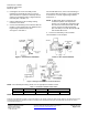
5. Connect the field wiring to the transmitter with the
positive (+) 26V supply lead to the PWR wire and
negative signal lead to the SIG wire.
See Figure 4 and Table 1.
For 544-562-XX
variants, connect the field wiring to
the transmitter with the positive (+) 26V supply lead
to terminal No. 1 and the negative signal lead to
terminal No. 2.
NOTE: In applications where condensate may
accumulate (chillers, low temperature
sensing, etc.) seal all wire connections with
RTV. RTV is included with kit 536-774-XX
variants
and can be ordered separately
(P/N. 535-495) for use with kits 536-767-XX
and 544-562-XX
variants.
6. Connect the field wiring at the controller.
The installation is now complete.
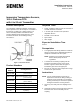
Figure 2. Pipe Surface Installation.
Figure 3. Pipe Joint Installation.
Figure 4. Wiring Connections for 4 to 20 mA Sensors.
NOTE: For individual panel wiring details, see the appropriate hardware manual.
Table 1. Transmitter Lead Wire Color Codes.
Terminal
PWR
SIG
RTD
Option 1
Red
Brown
Black
Orange
Option 2
Red
Black
White
White
NOTE: Wire colors vary by transmitter supplier.