
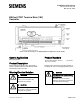
Installation Instructions


Document No. 550-144
Installation Instructions
October 26, 2016
Page 2 of 8 Siemens Industry, Inc.
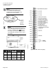
Accessories
Low cost temporary temperature
sensor, 10K thermistor with
RJ11, that enables space control
if the permanent room or duct
sensor is not installed (pack of
25).
540-658P25
Duct Temperature Sensor, NTC
10K Ω Type 2, 3" Probe for
Commissioning only
QAM1030.008P50
Expected Installation Time
New controller installation
10 Minutes
Replacement (old controller has
removable terminal blocks)
6 Minutes
Replacement (old controller does
not have removable terminal
blocks)
16 Minutes
NOTE:
You may require additional time for
database work at the field panel.
Required Tools and Equipment
Small flat-blade screwdriver (1/8-inch blade
width)
Cabling and connectors
Cordless drill/driver set
ESD wrist strap
Prerequisites
Wiring conforms to NEC and local codes and
regulations. For further information see the
Wiring Guidelines Manual
.
Room temperature sensor installed (optional).
24 Vac Class II power available.
Supply power to the unit is OFF.
Any application specific hardware or devices
installed.
Air velocity sensors installed in ducts.
NOTE:
If the controller is being installed on a
box with 1 or more stages of electric
heat, the 550-809 MOV with pre-
terminated spade connectors must be
installed across the manufacturer-
supplied airflow switch. MOVs can be
installed at the time the controller is
factory mounted; coordinate with the
box manufacturer prior to order
placement. For field installation, see
Metal Oxide Varistor Kit Installation
Instructions
(540-986).
NOTE:
A low-cost temporary RTS (540-
659P50) is available that plugs into the
RTS port on the controller, providing
temperature input and actual space
control until a permanent RTS is
installed.
Installation Instructions
NOTE:
All wiring must conform to national and
local codes and regulations (NEC, CE,
etc.).
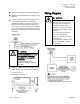
1. Secure the mounting rail in the controller’s
desired location.
2. Place the ESD wrist strap on your wrist and
attach it to a good earth ground.
3. Remove the controller from the static proof bag
and snap it into place on the mounting rail.
4. Connect the FLN.