
Installation Instructions


Document No. 550-144
Installation Instructions
October 26, 2016
Siemens Industry, Inc. Page 3 of 8
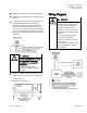
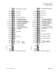
5. Connect the point wiring (see
Wiring Diagram
s).
6. Plug the room temperature sensor cable into the
RTS port.
7. Connect the power trunk. DO NOT apply power
to the controller without first consulting the
specialist. This TEC is designed to work with 2-
wire AC power (Neutral and Phase (hot) at 24
Vac +/-20%. Use of the earth terminal is optional
and if used it should be connected to the nearest
earth ground (building steel, conduit or duct work
(if earthed).
CAUTION
It is very important that the neutral
that supplies the TEC be earth
grounded at the source of the
24Vac power.
Possible erratic equipment
operation or damage if neutral is
left floating.
8. Connect the tubing from the air velocity sensor
pickup to the ports on the controller. Connect HI
to HI and LO to LO.
The installation is complete.
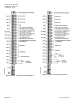
Wiring Diagram
CAUTION
The controller’s DOs control 24
Vac loads only. The maximum
rating is 12 VA for each DO. An
external interposing relay is
required for any of the following:
• VA requirements higher than the
maximum
• 110 or 220 Vac requirements
• DC power requirements
• Separate transformers used to
power the load
(for example part number 540-147,
Terminal Equipment Controller
Relay Module)
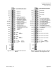
Wiring for AI with a 4 to 20 mA Sensor.