
Application


Sequence of Operation
Application Notes
18
Siemens Industry, Inc.
Application Note, App 6645
140-1172
2014-07-17
Application Notes
The controller keeps all associated equipment OFF. See the appropriate
Start-up
Procedures
for information on how to release the controller and its equipment to
application control.
Spare DOs can be used as auxiliary points that are controlled by the field panel
after being defined in the field panel’s database. If a cooling valve is not being
controlled by the application, DO 1 and DO 2 may be used as auxiliary motor
points. If a heating valve is not being controlled by the application, DO 3 and DO 4
may be used as auxiliary motor points. If using a pair of spare DOs to control a
motor, you must make sure that the motor setup, motor timing, and motor rotation
angle are enabled correctly before you unbundle VLV 1 COMD for DO 1 and DO 2
and VLV 2 COMD for DO 3 and DO 4.
See the
Start-up Procedures
on Asset Portal or InfoLink for more information.
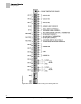
Wiring Diagram
CAUTION
The controller’s DOs control 24 Vac loads only. The maximum rating is 12 VA for
each DO. An external interposing relay is required for any of the following:
• VA requirements higher than the maximum
• 110 or 220 Vac requirements
• DC power requirements
• Separate transformers used to power the load
(for example part number 540-147, Terminal Equipment Controller Relay Module)
NOTE:
Thermistor inputs are 10K (default) or 100K software selectable (AUX TEMP AI X).
Wiring for AI with a 4 to 20 mA Sensor.