BACnet PTEC Controller Unit Conditioner - Fan Coil Unit Two-Stage Cooling and Electric Heat, Application 6646 Application Note 140-1173 2014-07-17 Building Technologies
Table of Contents Overview ............................................................................................................................. 5 BACnet .............................................................................................................................. 6 Hardware Inputs .................................................................................................................. 6 Room Unit Identification ...............................................................
Application Notes ............................................................................................................... 19 Wiring Diagram .................................................................................................................. 19 Application 6646 Point Database ................................................................................... 22 4 Siemens Industry, Inc.
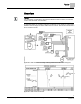
Overview BACnet Overview NOTE: For information on applications with Firmware Revision Bx40 or earlier, see InfoLink and/or Asset Portal for documentation. In Application 6646, the controller energizes a maximum of two stages of cooling and a maximum of three stages of electric heat in the fan coil unit. The fan coil unit also has a fan to circulate room air. Application 6646 Fan Unit Two-Stage Cooling and Electric Heat Control Diagram. Application 6646 Control Schedule. 5 Siemens Industry, Inc.
Overview BACnet BACnet The controller communicates using BACnet MS/TP protocol for open communications on BACnet MS/TP networks.
Overview Hardware Outputs Room Unit Identification For Analog Room Units – The revision number is visually identified by its case. For Digital Room Units (Firmware Revision 25 or earlier) – The revision number displays for 5 seconds when the room unit is first powered up. These room units will display laptop when a laptop is connected and will no longer update room temperature sensor values.
Sequence of Operation Control Temperature Setpoints Sequence of Operation The following paragraphs present the sequence of operation for the Siemens BACnet PTEC Unit Conditioner Controller. Control Temperature Setpoints This application has a number of different room temperature setpoints (DAY HTG STPT, NGT CLG STPT, RM STPT DIAL, etc.). The application actually controls using the CTL STPT.
Sequence of Operation Control Temperature Setpoints CTL STPT Using Standard/Absolute Mode (Digital Room Unit, Revision 26 and later) Digital Room Unit (2200/2300 Series Firmware Revision 26 and later) For all new digital room units, the value displayed and reported by the room unit is linked to the current heat/cool mode. When the mode changes, the value is automatically updated based on the new heat/cool mode.
Sequence of Operation Control Temperature Setpoints CTL STPT Using Standard/Absolute Mode (Analog or Digital Room Unit) Analog (Series 1000) or Digital Room Units (Firmware Revision 25 or earlier) NOTE: 2200/2300 digital room units with Firmware Revision 25 or earlier are only compatible with standard room unit functionality (no warmer/cooler). When STPT SPAN is set to 0, CLT STPT is set based on the value of the setpoint dial and the setpoint deadband.
Sequence of Operation Heating/Cooling Switchover Minimum lowest adjusted setpoint value is equal to DAY CLG STPT or DAY HTG STPT - STPT SPAN Maximum highest adjusted setpoint value is equal to DAY CLG STPT or DAY HTG STPT + STPT SPAN The full range of the analog room unit slider will be mapped to a range of minimum setpoint value to maximum setpoint value. CTL STPT is set equal to RM STPT DIAL.
Sequence of Operation Heating/Cooling Switchover When the controller is in cooling mode, the heating switchover setpoint is as follows: Heating switchover point is equal to RM STPT DIAL – DAY CLG STPT + DAY HTG STPT When the controller is in heating mode, the cooling switchover setpoint is as follows: Cooling switchover point is equal to RM STPT DIAL – DAY HTG STPT + DAY CLG STPT Example DAY CLG STPT = 74 and DAY HTG STPT = 70 In cooling mode, when the user adjusts the setpoint value on the room un
Sequence of Operation Room Temperature, Room Temperature Offset and CTL TEMP Heating/Cooling Switchover Using Standard/Absolute Mode (Analog Room Unit) Analog (Series 1000) or Digital Room Units (Firmware Revision 25 or earlier) The difference between day heating and day cooling setpoint establishes the separation for heat/cool switchover points (deadband = DAY CLG STPT – DAY HTG STPT).
Sequence of Operation Day and Night Modes If CTL TEMP is not overridden, then: The current value of ROOM TEMP (normal or overridden) is used to determine the value of CTL TEMP. If ROOM TEMP has a status of Failed, then last known good value of ROOM TEMP is used to determine the value of CTL TEMP. Day and Night Modes The day/night status of the space is determined by the status of DAY.NGT.
Sequence of Operation Cooling Operation Cooling Operation In cooling mode, the controller uses CTL STPT and CTL TEMP as inputs for the cooling loop. The cooling loop controls up to two stages of cooling as defined by the value of CLG STG CNT. The staged cooling operates as follows: CLG STG 1 will turn ON when CLG LOOPOUT > CLG 1 ON , provided that CLG STG 1 has been OFF for at least the time set in CLG MIN OFF .
Sequence of Operation Fan Operation Example If the duty cycle is 10 minutes (HTG STG TIME = 10 minutes) and the heating loop is calling for 60% of heating (HTG LOOPOUT = 60%) for every 10-minute period, the stages of electric auxiliary heat cycle are as follows: Stage 1: minutes ON OFF Stage 2: minutes ON OFF Stage 3: minutes ON OFF With 1 stage of electric heat: 64 -- -- With 2 stages of electric heat: 10 0 28 -- With 3 stages of electric heat: 10 0 82 0 10 Fan Operation NOTE: If this appli
Sequence of Operation Room Unit Operation Floating Control Actuation Auto-correct In addition to the existing options for floating control actuator full stroke actions, all floating control actuators are provided with additional logic to fully drive open or closed when commanded to 100% or 0%. Room Unit Operation Sensor Select SENSOR SEL is a configurable, enumerated point (values are additive). This point tells the controller what type of room unit is being used and how to handle loss of data.
Sequence of Operation Auto Discovery Room CO2 RM CO2 displays the CO2 value in units of parts-per-million (PPM). RM CO2 (from the digital 2200/2300 room units) can be used with PPCL in the PTEC controller or unbundled for control or monitoring purposes. Room RH RM RH displays the relative humidity value in percent. RM RH can be used for PPCL in the PTEC or unbundled for control or monitoring purposes.
Sequence of Operation Application Notes Application Notes The controller keeps all associated equipment OFF. See the appropriate Start-up Procedures for information on how to release the controller and its equipment to application control. Spare DOs can be used as auxiliary points that are controlled by the field panel after being defined in the field panel’s database. DO 3, DO 4, and DO 5 control the stages of electric heat.
Sequence of Operation Wiring Diagram NOTE: If the voltage/current switch is set to current and a 4 to 20 mA sensor is connected to an AI, then special wiring requirements must be followed. 20 Siemens Industry, Inc.
Sequence of Operation Wiring Diagram Application 6646 - Fan Coil Unit 2-Stage Cooling and Electric Heat. 21 Siemens Industry, Inc.
Application 6646 Point Database Application 6646 Point Database Object Type1 Object Instance (Point Number) Object Name (Descriptor) Factory Default (SI Units)2 Eng Units (SI Units) Range Active Text Inactive Text AO 1 CTLR ADDRESS 255 -- 0-255 -- -- AO 2 APPLICATION 6691 -- 0-32767 -- -- AO 3 RMTMP OFFSET 0.0 (0.0) DEG F (DEG C) -31.75-32 -- -- AI {04} ROOM TEMP 74.0 (23.44888) DEG F (DEG C) 48-111.75 -- -- BO {05} HEAT.
Application 6646 Point Database Object Type1 Object Instance (Point Number) Object Name (Descriptor) Factory Default (SI Units)2 Eng Units (SI Units) Range Active Text Inactive Text AO {32} AOV1 0 VOLTS 0-10.23 -- -- AO {33} AOV2 0 VOLTS 0-10.23 -- -- AO {34} AOV3 0 VOLTS 0-10.
Application 6646 Point Database Object Type1 Object Instance (Point Number) Object Name (Descriptor) Factory Default (SI Units)2 Eng Units (SI Units) Range Active Text Inactive Text AO 84 STAGE FAN 10 PCT 0-102 -- -- AO 85 SWITCH LIMIT 5.2 PCT 0-102 -- -- AO 86 SWITCH TIME 10 MIN 0-255 -- -- AO 88 HTG STG CNT 1 -- 0-255 -- -- AO 89 HTG STG TIME 10 MIN 0-255 -- -- AO 90 SWITCH DBAND 1.0 (0.56) DEG F (DEG C) 0-63.75 -- -- AO {92} CTL STPT 74.0 (23.
Issued by Siemens Industry, Inc. Building Technologies Division 1000 Deerfield Pkwy Buffalo Grove IL 60089 Tel. +1 847-215-1000 Document ID 140-1173 Edition 2014-07-17 © 2014 Copyright Siemens Industry, Inc. Technical specifications and availability subject to change without notice.