
Operating Instructions
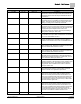
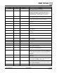
Table Of Contents
- How To Use This Manual
- Chapter 1 – Product Overview
- Chapter 2 – Applications
- Basic Operation
- Application 6665 Constant Volume Two Inlet Sensors with Optional Reheat
- Application 6666 Constant Volume One Inlet and One Outlet Sensor with Optional Reheat
- Application 6667 VAV - Two Inlet Sensors with Optional Reheat
- Application 6668 VAV - One Inlet and One Outlet Sensor with Optional Reheat
- Application 6669 VAV with Changeover
- Application 6693 Dual Duct 2 AVS Slave Mode
- Chapter 3 – Point Database
- Chapter 4 – Basic Service and Maintenance
- Glossary
- Index

Chapter 3 – Point Database
21
Siemens Industry, Inc. Owner's Manual 125-5069
2014-09-03
Descriptor
Address
1
Application
Description
RM STPT MAX 12 6665-6669 The maximum temperature setpoint in degrees that the
controller can use from the setpoint dial. This overrides any
temperature setpoint from the setpoint dial that falls above
this maximum.
RM STPT DIAL {13} All The temperature setpoint in degrees from the room
temperature sensor (not available on all temperature sensor
models). This setpoint will be used for control in day mode
(heating or cooling) when enabled by STPT DIAL.
STPT DIAL 14 6665-6669 YES indicates that there is a room setpoint dial on the room
temperature sensor and it should be used as the temperature
setpoint for control in day/occupied mode. NO indicates that
the appropriate preset setpoint will be used as the
temperature setpoint for control in day/occupied heating or
cooling mode. Valid input: YES or NO.
AUX TEMP AI5 {15} 6665-6669 Actual reading from a 100K or 10K thermistor connected to
the controller's AI 5 input. When a thermistor is connected at
AI 5, DI 5 is not available. See
DI 5
.
HTG DUCTTEMP {15} 6669 Actual reading from a 100K or 10K thermistor located in the
hot duct connected to the controller’s AI 5 input. When a
thermistor is connected at AI 5, DI 5 is not available. See
DI
5
.
FLOW START 16 6667-6669 Determines how the damper modulation will be sequenced
while in heating mode. When HTG LOOPOUT is above this
value, then FLOW STPT starts to increase.
FLOW END 17 6667-6669 Determines how the damper modulation will be sequenced
while in heating mode. When HTG LOOPOUT is below this
value, then FLOW STPT starts to decrease.
WALL SWITCH 18 All YES indicates that the controller is to monitor the status of a
wall switch that is connected to UI 2. NO indicates that the
controller will not monitor the status of a wall switch, even if
one is connected. Valid input: YES or NO.
DI OVRD SW {19} All Actual indication of the status of the override switch (not
physically available on all temperature sensor models) at the
room temperature sensor. ON indicates that the switch is
being pressed. OFF indicates that the switch is released.
Valid input: ON or OFF.
OVRD TIME 20 6665-6669 The amount of time in hours that the controller will operate in
day/occupied mode when the override switch is pressed
while the controller is in night/unoccupied mode.
NGT OVRD {21} 6667-6669 Indicates the mode that the controller is operating in with
respect to the override switch. NIGHT indicates that the
switch has not been pressed and the override timer is not
active. DAY indicates that the switch has been pressed and
the override timer is active. The controller then uses a day
mode temperature setpoint. This point is only in effect when
DAY.NGT indicates night mode.
UNOCC OVRD {21} 6665, 6666 Indicates the mode that the controller is operating in with
respect to the override switch. UNOCC indicates that the
switch has not been pressed and the override timer is not
active. OCC indicates that the switch has been pressed and
the override timer is active. The controller then uses an
occupied mode temperature set point. This point is only in
effect when OCC.UNOCC indicates UNOCC mode.
REHEAT START 22 6667-6669 Determines how the reheat modulation will be sequenced