
Operating Instructions
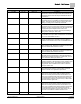
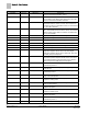
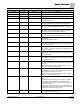
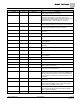
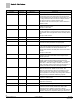
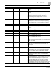
Table Of Contents
- How To Use This Manual
- Chapter 1 – Product Overview
- Chapter 2 – Applications
- Basic Operation
- Application 6665 Constant Volume Two Inlet Sensors with Optional Reheat
- Application 6666 Constant Volume One Inlet and One Outlet Sensor with Optional Reheat
- Application 6667 VAV - Two Inlet Sensors with Optional Reheat
- Application 6668 VAV - One Inlet and One Outlet Sensor with Optional Reheat
- Application 6669 VAV with Changeover
- Application 6693 Dual Duct 2 AVS Slave Mode
- Chapter 3 – Point Database
- Chapter 4 – Basic Service and Maintenance
- Glossary
- Index

Chapter 3 – Point Database
22
Siemens Industry, Inc. Owner's Manual 125-5069
2014-09-03
Descriptor
Address
1
Application
Description
while in heating mode. When HTG LOOPOUT is above this
value, then the reheat modulates upward.
REHEAT END 23 6667-6669
Determines how the reheat modulation will be sequenced
while in heating mode. When HTG LOOPOUT is below this
value, then the reheat modulates downward.
DI 2 {24} All Actual status of a contact connected to the controller at DI 2.
ON indicates that the contact is closed; OFF indicates that
the contact is open. If a wall switch is used, it is connected to
DI 2. See
WALL SWITCH
.
DI 3 {25} All Actual status of a contact connected to the controller at DI
3/AI 3. ON indicates that the contact is closed; OFF indicates
that the contact is open. When a contact is connected at DI
3, AI 3 is not available.
HTGFLO PGAIN 26 6665-6667, 6669 The proportional gain value for the heating flow control loop.
TOTFLO PGAIN 26 6668 The proportional gain value for the total flow control loop.
HTGFLO IGAIN 27 6665-6667, 6669 The integral gain value for the heating flow control loop.
TOTFLO IGAIN 27 6668 The integral gain value for the total flow control loop.
HTGFLO DGAIN 28 6665-6667, 6669 The derivative gain value for the heating flow control loop.
TOTFLO DGAIN 28 6668 The derivative gain value for the total flow control loop.
DAY.NGT {29} 6667-6669, 6693 Indicates the mode in which the controller is operating. Day
temperature setpoints will be used in day mode. Night
temperature setpoints will be used in night mode. This point
is normally set by the field panel.
OCC.UNOCC {29} 6665, 6666 Indicates the mode in which the controller is operating.
Occupied temperature setpoints will be used in OCC mode.
Unoccupied temperature setpoints will be used in UNOCC
mode. This point is normally set by the field panel.
AIR VOLUME 2 30 6693 Actual amount of air in CFM (LPS) currently passing through
the air velocity sensor 2.
HTG VOLUME {30} 6665, 6667, 6669 Actual amount of air in CFM (LPS) currently passing through
the hot air duct.
TOT VOLUME {30} 6666, 6668 Actual amount of air in CFM (LPS) currently passing through
the discharge air duct.
UNOCC FLOW {31} 6665, 6666 The amount of air in CFM (LPS) to be supplied to the space
during unoccupied periods.
CLG FLOW MAX {32} 6667-6669 The maximum amount of air in CFM (LPS) to be supplied to
the space in cooling mode.
OCC FLOW {32} 6665, 6666 The amount of air in CFM (LPS) to be supplied to the space
during occupied periods.
TOT FLOW MIN {33} 6667-6669 The total minimum amount of air in CFM (LPS) to be
supplied to the space.
HTG FLOW MAX {34} 6667, 6669 The maximum amount of air in CFM (LPS) to be supplied to
the space in heating mode.
TOT FLOW MAX 34 6668 The total maximum amount of air in CFM (LPS) to be
supplied to the space.
AIR VOLUME 1 35 6693 Actual amount of air in CFM (LPS) currently passing through
the air velocity sensor 1.
CLG VOLUME {35} 6665-6669 Actual amount of air in CFM (LPS) currently passing through