
Operating Instructions
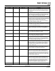
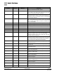
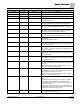
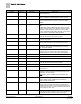
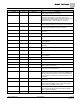
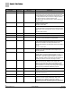
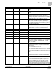
Table Of Contents
- How To Use This Manual
- Chapter 1 – Product Overview
- Chapter 2 – Applications
- Basic Operation
- Application 6665 Constant Volume Two Inlet Sensors with Optional Reheat
- Application 6666 Constant Volume One Inlet and One Outlet Sensor with Optional Reheat
- Application 6667 VAV - Two Inlet Sensors with Optional Reheat
- Application 6668 VAV - One Inlet and One Outlet Sensor with Optional Reheat
- Application 6669 VAV with Changeover
- Application 6693 Dual Duct 2 AVS Slave Mode
- Chapter 3 – Point Database
- Chapter 4 – Basic Service and Maintenance
- Glossary
- Index

Chapter 3 – Point Database
24
Siemens Industry, Inc. Owner's Manual 125-5069
2014-09-03
Descriptor
Address
1
Application
Description
MTR1 CMD {48} 6693 The value to which the Motor 1 actuator is commanded in
percent of full travel.
CLG DMP POS {49} 6665-6669 The current position of the damper motor in percent of full
travel. This value is calculated based on motor run time.
MTR1 POS {49} 6693 The current position of Motor 1 in percent of full travel. This
value is calculated based on motor run time. See
MTR1
TIMING
.
DO 8 {50} All Digital output 8 controls a 24 Vac load with an ON or OFF
status.
In applications with CAL MODULE set to YES, this output
controls Autozero Module 2 for calibration of the controller’s
internal air velocity transducer piped to the hot duct flow
sensor in Applications 6665, 6667, and 6669, or the volume
duct flow sensor in Applications 6666 and 6568.
MTR1 TIMING 51 All The time, in seconds, required for the Motor 1 actuator to
travel from full closed to the full open position.
HTG DMP CMD {52} 6665-6669
The value to which the hot duct damper motor is commanded
in percent of full travel.
MTR2 COMD {52} 6693 The value to which the Motor 2 actuator is commanded in
percent of full travel (for use as an auxiliary slave point).
HTG DMP POS 53 6665-6669 The current position of the hot duct damper motor in percent
of full travel. This value is calculated based on motor run
time. See
MTR2 TIMING
.
MTR2 POS {53} 6693 The current position of the Motor 2 actuator in percent of full
travel (for use as an auxiliary slave point). This value is
calculated based on motor run time. See
MTR2 TIMING
.
HTG FLO COEF 54 6665,6667,6669 Calibration factor for the hot duct flow sensor.
FLOW COEFF 2 54 6693 Calibration factor for the airflow sensor 2.
TOT FLO COEF 54 6666, 6668 Calibration factor for the volume duct flow sensor.
MTR2 TIMING 55 All The time, in seconds, required for the Motor 2 actuator to
travel from full closed to the full open position.
DPR1 ROT ANG 56 All The number of degrees that damper 1 is free to travel.
DPR2 ROT ANG 57 All The number of degrees that damper 2, the hot duct damper,
is free to travel.
MTR SETUP 58 All The configuration setup code for Motors 1 and 2. This
enables the motors individually and sets each motor to be
either direct or reverse acting.
Note:
When a motor is enabled, its associated DOs are
enabled.
DO DIR.REV 59 All The configuration setup code for DOs. Allows the DOs to be
direct or reverse acting (enabled equals energized or
disabled equals de-energized).
DUCT AREA 2 60 6693 Area, in square feet (square meters), of duct 2 where the air
velocity sensor is located. This value is calculated by the
portable operator’s terminal or by the field panel depending
on duct shape and size. It is used in calculating all points in
units of CFM, CF, LPS, and L.
HTGDUCT AREA 60 6665,6667,6669 Area, in square feet (square meters), of the hot duct where
the air velocity sensor is located. This value is calculated by
the portable operator’s terminal or by the field panel