BACnet PTEC Controller Constant Volume with Hot Water Reheat, Application 6663 Application Note 140-1109 2014-10-27 Building Technologies
Table of Contents Overview ............................................................................................................................. 4 BACnet .............................................................................................................................. 5 Hardware Inputs .................................................................................................................. 5 Room Unit Identification ...............................................................
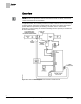
Overview BACnet Overview NOTE: For information on applications with Firmware Revision Bx40 or earlier, see InfoLink and/or Asset Portal for documentation. In Application 6663, the controller provides a constant volume of air to the room during occupied periods, and a lower constant volume of air to the room during unoccupied periods. Reheat is provided by modulating a hot water valve.
Overview BACnet Application 6663 Control Schedule. BACnet The controller communicates using BACnet MS/TP protocol for open communications on BACnet MS/TP networks.
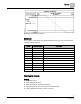
Overview Hardware Outputs Digital Night mode override (optional) Wall switch (optional) Spare DI NOTE: Digital Room Units (Firmware Revision 26 and later) will update their controlled inputs without putting them Out Of Service. However, a command from an external source through the digital room unit will put the associated BACnet Input point Out Of Service. Room Unit Identification For Analog Room Units – The revision number is visually identified by its case.
Sequence of Operation Control Temperature Setpoints Sequence of Operation The following paragraphs present the sequence of operation for Application 6663 -Constant Volume with Hot Water Reheat. NOTE: This application will not automatically switch between heating and cooling. If a seasonal switchover (for example, summer to winter) is to occur, PPCL in the controller or in the field panel must command HEAT.COOL. This allows the controller to use the appropriate setpoints for the season.
Sequence of Operation Control Temperature Setpoints CTL STPT Using Standard/Absolute Mode (Digital Room Unit, Revision 26 and later) Digital Room Unit (2200/2300 Series Firmware Revision 26 and later) For all new digital room units, the value displayed and reported by the room unit is linked to the current heat/cool mode. When the mode changes, the value is automatically updated based on the new heat/cool mode.
Sequence of Operation Control Temperature Setpoints CTL STPT Using Standard/Absolute Mode (Analog or Digital Room Unit) Analog (Series 1000) or Digital Room Units (Firmware Revision 25 or earlier) NOTE: 2200/2300 digital room units with Firmware Revision 25 or earlier are only compatible with standard room unit functionality (no warmer/cooler). When STPT SPAN is set to 0, CLT STPT is set based on the value of the setpoint dial and the setpoint deadband.
Sequence of Operation Heating/Cooling Switchover CTL STPT is set equal to RM STPT DIAL. The values for RM STPT MINand RM STPT MAX will be applied to limit RM STPT DIAL before it is copied into CTL STPT. Example in Cooling Mode If the STPT SPAN is set to 2.0 degrees, and the DAY CLG STPT is 76°F, the room unit slider will adjust the cooling setpoint from 74°F to 78°F. Heating/Cooling Switchover This application does not perform an automatic heating/cooling switchover function.
Sequence of Operation Hot Water Reheat FLOW is the input value for the flow loop. It is calculated as a percentage based on where AIR VOLUME is between 0 cfm (LPS) and OCC FLOW. In the following text, this percentage is referred to as % flow. If AIR VOLUME equals 0 cfm (LPS), then FLOW is 0% flow. If AIR VOLUME equals OCC FLOW, then FLOW is 100% flow. The FLOW STPT percentage that corresponds to UNOCC FLOW is calculated as: (UNOCC FLOW ÷ OCC FLOW) × 100% flow.
Sequence of Operation Room Unit Operation Floating Control Actuation Auto-correct In addition to the existing options for floating control actuator full stroke actions, all floating control actuators are provided with additional logic to fully drive open or closed when commanded to 100% or 0%. Room Unit Operation Sensor Select SENSOR SEL is a configurable, enumerated point (values are additive). This point tells the controller what type of room unit is being used and how to handle loss of data.
Sequence of Operation Auto Discovery Room CO2 RM CO2 displays the CO2 value in units of parts-per-million (PPM). RM CO2 (from the digital 2200/2300 room units) can be used with PPCL in the PTEC/ATEC controller or unbundled for control or monitoring purposes. Room RH RM RH displays the relative humidity value in percent. RM RH can be used for PPCL in the PTEC or unbundled for control or monitoring purposes. RM RH displays the relative humidity value in percent.
Sequence of Operation Application Notes Application Notes If temperature swings in the room are excessive or there is trouble maintaining the room temperature setpoint, the temperature loop needs to be tuned. If FLOW is oscillating while FLOW STPT is constant, then the flow loop requires tuning. The controller as shipped from the factory keeps all associated equipment OFF. See the Start-up document for how to release the controller and its equipment to application control.
Sequence of Operation Wiring Diagrams CAUTION Each 4-20 mA sensor requires a SEPARATE dedicated power limited 24 VDC power supply. DO NOT use the same transformer to power both the sensor and the controller. NOTE: If the voltage/current switch is set to current and a 4 to 20 mA sensor is connected to an AI, then special wiring requirements must be followed. 15 Siemens Industry, Inc.
Sequence of Operation Wiring Diagrams Application 6663 – Constant Volume with Hot Water Reheat. 16 Siemens Industry, Inc.
Application 6663 Point Database Application 6663 Point Database Object Type1 Object Instance (Point Number) Object Name (Descriptor) Factory Default (SI Units)2 Eng Units (SI Units) Range Active Text Inactive Text AO 1 CTLR ADDRESS 255 -- 0-255 -- -- AO 2 APPLICATION 6694 -- 0-32767 -- -- AI {04} ROOM TEMP 74.0 (23.44888) DEG F (DEG C) 48-111.75 -- -- BO {05} HEAT.COOL COOL -- Binary HEAT COOL AO 6 OCC CLG STPT 70.0 (21.20888) DEG F (DEG C) 48-111.
Application 6663 Point Database Object Type1 Object Instance (Point Number) Object Name (Descriptor) Factory Default (SI Units)2 Eng Units (SI Units) Range Active Text Inactive Text BO {43} DO 3 OFF -- Binary ON OFF BO {44} DO 4 OFF -- Binary ON OFF BO {45} DO 5 OFF -- Binary ON OFF BO {46} DO 6 OFF -- Binary ON OFF BO {47} DO 7 OFF -- Binary ON OFF AO {48} DMPR COMD 0 PCT 0-102 -- -- AO {49} DMPR POS 0 PCT 0-102 -- -- BO {50} DO 8 OFF --
Application 6663 Point Database Object Type1 Object Instance (Point Number) Object Name (Descriptor) Factory Default (SI Units)2 Eng Units (SI Units) Range Active Text Inactive Text (SQ M) AO 98 LOOP TIME 5 SEC 0-255 -- -- AO {99} ERROR STATUS 0 -- 0-255 -- -- AO {102} AOV 1 0 VOLTS 0-10.23 -- -- AO {103} AOV 2 0 VOLTS 0-10.23 -- -- AO {104} AOV 3 0 VOLTS 0-10.23 -- -- AI {105} AI 3 0 PCT 0-102 -- -- AI {106} AI 4 74.0 (23.
Issued by Siemens Industry, Inc. Building Technologies Division 1000 Deerfield Pkwy Buffalo Grove IL 60089 Tel. +1 847-215-1000 Document ID 140-1109 Edition 2014-10-27 © 2014 Siemens Industry, Inc. Technical specifications and availability subject to change without notice.