
Application

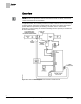

Sequence of Operation
Control Temperature Setpoints
9
Siemens Industry, Inc.
Application Note, App 6663
140-1109
2014-10-27
CTL STPT Using Standard/Absolute Mode (Analog or Digital
Room Unit)
Analog (Series 1000) or Digital Room Units (Firmware Revision 25 or
earlier)
NOTE:
2200/2300 digital room units with Firmware Revision 25 or earlier are only compatible
with standard room unit functionality (no warmer/cooler).
When STPT SPAN is set to 0, CLT STPT is set based on the value of the setpoint dial
and the setpoint deadband.
The setpoint deadband is the difference between the cooling and heating day setpoints
(DAY CLG STPT DAY – HTG STPT). The setpoint deadband can be disabled by
setting DAY HTG STPT equal to DAY CLG STPT. When DAY HTG STPT does not
equal DAY CLG STPT, a setpoint deadband (or zero energy band) is used.
The following values are used in the calculation of CTL STPT:
Deadband
is the value of the difference between DAY CLG STPT and DAY HTG
STPT and is used to establish the current heating and cooling setpoints.
Deadband
= (DAY CLG STPT – DAY HTG STPT)
CTL STPT is calculated as follows:
With Deadband disabled:
CTL STPT = RM STPT DIAL
With Deadband enabled in Heat Mode:
CTL STPT = RM STPT DIAL – 0.5 ∗
Deadband
With Deadband enabled in Cool Mode:
CTL STPT = RM STPT DIAL + 0.5 ∗
Deadband
CTL STPT is limited between the value of RM STPT MIN and RM STPT MAX
CTL STPT Using Warmer/Cooler Mode (Analog Room Unit
Only)
Analog Room Unit (Series 1000)
NOTE:
The warmer-cooler function for analog room units (Series 1000) use the
warmer/cooler scale of units with a warmer/cooler housing.
When SPTP SPAN > 0, the minimum and maximum values for RM STPT DIAL are
calculated as follows:
Minimum lowest adjusted setpoint value is equal to DAY CLG STPT or DAY HTG
STPT - STPT SPAN
Maximum highest adjusted setpoint value is equal to DAY CLG STPT or DAY HTG
STPT + STPT SPAN
The full range of the analog room unit slider will be mapped to a range of
minimum
setpoint value to maximum setpoint value.