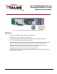
UV with Dehumidification and Heating/Chilled Water Control Application Data Sheet Figure 1. Unit Ventilator with Dehumidification and Heating/Chilled Water Control. Features • Certified to fit LonMark® Space Comfort Control Profile 8505. • Dehumidification cycle to maintain comfort and IAQ. • Discharge temperature control for smooth transitions between psychometric processes. • PID control minimizes offset and maintains tight control.
Sequence of Operation General This example configuration uses a chilled water coil for cooling and dehumidification, a hot water heating coil, and an outdoor air damper for cooling and ventilation. The Predator monitors the temperature and humidity in the room and compares them to selected setpoints. As the monitored conditions change, the control algorithm operates the heating and cooling equipment to efficiently maintain the specified room setpoints.
Unoccupied Cooling Mode When the space temperature rises beyond the unoccupied cooling setpoint, the fan starts. If free cooling is available, and the OA damper is enabled for unoccupied operation, the Predator modulates the damper to maintain the discharge setpoint and cools the space. If further cooling is required, the Predator modulates the chilled water valve to maintain the discharge setpoint. When the space temperature drops, the valve and damper close and the fan shuts off.
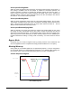
Dehumidification Sequence Diagram 100% Open Heating Valve Damper Minimum Cooling Valve Outdoor Air Damper 0% Optional Functions Room Temperature Sensor Sharing The Predator Room Temperature Sensor may share its value with other controllers on the LONTalk® network via a network binding. This is most commonly done when multiple terminal units serve a room or area. Wall Switch An optional maintained contact wall switch may be used to control the occupancy mode of a room.
Relief Fan The Predator supports operation of a two-state relief device: fan or damper. When the supply fan is on and the OA damper opens beyond a selected range, the relief device is activated. High Speed Fan Setting The controller may operate a separate output to run the supply fan at high speed. This is applied whenever the unit starts in the unoccupied mode. It is also applied for the first few seconds of occupancy.
Hardware Map – Unit Vent with Dehumidification Configuration Element Property StatTemp StatSetpt StatOvrd IN1 inputs IN2 IN3 IN4 IN5 IN6 OUTA1 OUTA2 OUTA3 OUTD1 OUTD2 outputs OUTD3 OUTD4 OUTD5 OUTD6 OUTD7 OUTD8 Input/Output TEMP TEMP DI DI, TEMP DI, TEMP DI, PCT, TEMP DI, PCT, TEMP DI, PCT, TEMP DI, PCT, TEMP AO AO AO DO, FLT_MTR DO, FLT_MTR DO, FLT_MTR DO, FLT_MTR DO, FLT_MTR DO, FLT_MTR DO, FLT_MTR DO, FLT_MTR Factory Hardware Setting (Unit Ventilator CW) SPACE_TEMP SPACE_SETPT_TEMP STAT_SWITCH_DI DISCH
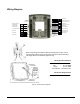
Wiring Diagram OA Damper Terminal Heat coil opt Terminal Cool coil opt Terminal Fan High Speed Term Fan Discharge Air Temp 10K thermistor Exhaust Fan Mixed Air Temp 10K thermistor Terminal HW Coil Condensate overflow Terminal HW Coil Space RH Terminal CW Coil Terminal CW Coil Fan Status Spare Output Spare input Note: Route wiring from either the bottom opening when using a J-box or from the base sides as shown in the picture when flat or din rail mounting.
Bill of Materials F D E C A G B Tag A B Description Predator UV with Dehumidification AHU 6IN, 8DO, 3AO, 1RTS Predator Full Point Wiring Base Predator Room Sensors: Sensing Only Override Setpoint Temperature Display Setpoint and Override Override and Temperature Display Setpoint and Temperature Display Setpoint, Override, and Temperature Display C D Not shown E F G Page 8 of 12 Predator Room Sensors without Logo’s: No Logo Sensing Only No Logo Setpoint No Logo Setpoint and Override No Logo S
Configuration Tables The application configuration tables below are typical for a UV with Dehumidification Application Component Configuration Item Element Unit Vent Core nciSetPnts OccupiedClg* StandbyClg Desired Setting (n/a if standby mode is not used) UnoccupiedClg OccupiedHtg* StandbyHtg UnoccupiedHtg htgClgSwit DmdDeadband TmpDeadband TIP: Usually set to zero (default) unless the heating and cooling setpoints are very close. TimeDelay TIP: Five minute default usually works well.
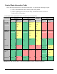
Control Mode Interaction Table Due to the large horizontal size of the control mode chart, it is split into the following two parts: • Chart 1: Dehumidification, Heat, Warm-up and Cooling Modes • Chart 2: Night Purge, Pre-cool, Off, Fan Only, Condensate Overflow, Fan Proof Failure and Low Temp Modes Control Mode Chart 1 (Dehumidification, Heat, Warm-up and Cool Modes) Dehumid Occ Term Htg Coil (HW) Heat Loop Unocc Heat Loop Heat Occ Heat Loop Warmup Unocc Cool Occ Unocc Closed Closed Off Off
Chart 2: Night Purge, Pre-cool, Off, Fan Only, Condensate Overflow, Fan Proof and Low Temp Modes Night Purge Pre-Cool Off Fan Only Condensate Overflow Fan Proof Failure Low Temp Term Htg Coil (HW) Closed Closed Closed Closed Closed Closed Open Staged Heat (Elec) Off Off Off Off Off Off Off Fan Demand On Off On Off Off Off Closed Closed Closed Closed Closed Closed Closed Closed Closed Open Off Off Off Off Off Cycle OA Dmpr Trm Clg Coil Relief Fan Cool Loop Co
Siemens Building Technologies, Inc. HVAC Products 1000 Deerfield Parkway Buffalo Grove, Illinois 60089 Phone 847-215-1000 www.staefa.com Copyright 2004 by Siemens Building Technologies, Inc. Page 12 of 12 Document No.