
Data Sheet for Product
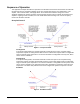
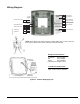

Table Of Contents
- Figure 1. Dual Duct VAV Box with Two Inlet Flow Sensors.
- Figure 2. Dual Duct VAV Box with One Inlet and One Discharge Flow Sensor.
- Features
- Sequence of Operation
- Dual Cold
- Dual Hot
- Morning Warm-up/ Pre-Cool
- Off
- Test/Calibrate
- Occupancy Control
- Special Features
- Hardware Map – Dual Duct VAV/CV
- Wiring Diagram
- Bill of Materials
- Configuration Tables
- Control Mode Interaction Table –Dual Duct VAV with QVM
- Control Mode Interaction Table –Dual Duct CV with QVM

Low Flow Dual Duct VAV/CV
with QVM
Application Data Sheet
Figure 1. Dual Duct VAV Box with Two Inlet Flow
Sensors.
Figure 2. Dual Duct VAV Box with One Inlet and One
Discharge Flow Sensor.
NOTE: The
source temperature sensor can be mounted in either hot or cold depending upon application usage.
Features
• Flow sensors can be installed in cold duct and hot duct, or cold duct and discharge duct.
• Operates dual cold/dual hot sequence, when both supply ducts use same temperature air.
• Application control of zone lighting reduces installation costs and provides energy savings.
• Advanced PID control minimizes offset and maintains tight setpoint control.
• Unique damper logic minimizes damper repositions, extending life of actuators.
• Standby mode enables energy savings during occupied hours for rooms that are not always used.
When occupants are sensed, the controller quickly responds to maintain comfort levels.
• Diversity control, through a demand limit input, maximizes comfort by maintaining even air distribution
to all zones during morning warm-up or pre-cool operation.
Document No. 588-023 January 2009