
User Guide


Flowrite 599 Series Two-Way Valves, 1/2 to 2-Inch, Bronze Body, ANSI 250 Technical Instructions
Document Number 155-184P25
August 25, 2009
Siemens Industry, Inc. Page 11
Sizing
The sizing of a valve is important for correct system operation. An undersized valve will
not have sufficient capacity at maximum load. An oversized valve can initiate cycling
and the seat and throttling plug can be damaged because of the restricted opening.
Correct sizing of the control valve for actual expected conditions is considered essential
for good control.
The following variables must be determined:
• The medium to be controlled, such as steam, water, etc.
• The maximum inlet temperature and pressure of the medium at the valve.
• The pressure differential that will exist across the valve under maximum load
demand.
• The maximum capacity the valve must deliver.
• The maximum line pressure differential the valve actuator must close against.
• See the Control Valve Selection and Sizing (AB-1) section of HVAC
Systems/Controls Reference Data (125-1853) for further recommendations.
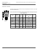
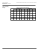
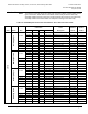
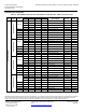
• See Tables 3 through 6 for valve capacities.
Mounting and
Installation
• Install the valve so that the flow follows the direction of the arrow indicated on the
valve body.
• For best performance, install the valve assembly with the actuator above the valve
body. The valve and actuator can be installed in any position between vertical and
horizontal. Siemens Building Technologies does not recommend installing the valve
assembly so that the actuator is below horizontal or upside down.
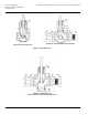
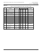
• Allow sufficient space for servicing the valve and actuator. See Table 12 for valve
body dimensions. See Figure 6 and Table 11 for dimensions of the service envelope
recommended around the actuator.
NOTE: Instructions for field mounting an actuator, wiring diagrams, and start-up are
covered in the Technical Instructions and Installation Instructions for each
actuator.