
Data Sheet for Product

Technical Instructions Cast Iron Flange Dimensions for 2-1/2 through 6-inch Valves
Document Number 155-303P25
March 7, 2005
Information in this publication is based on current specifications. The company reserves the right to make changes in specifications and models as
design improvements are introduced. Product or company names mentioned herein may be the trademarks of their respective owners.
© 2005 Siemens Industry, Inc.
Siemens Industry, Inc.
Building Technologies Division
1000 Deerfield Parkway
Buffalo Grove, IL 60089
+ 1 847-215-1000
Your feedback is important to us. If you have comments
about this document, please send them to
sbt_technical.editor@siemens.com
Document No. 155-303P25
Printed in the USA
Page 2
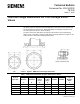
Dimensions
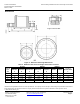
Figure 2. ANSI Class 250 Flange Dimensions.
Table 2. ANSI Class 250 Cast Iron Flanges. Dimensions in Inches.
Flanges
Drilling
Bolting
Nominal
Pipe
Size
Flange
Diameter
A
Flange
Thickness
B
Diameter of
Raised Face
C
Diameter of
Bolt Circle
D
Diameter of
Bolt Holes
E
Number
of Bolts
Diameter
of Bolts
Length of
Machine Bolts
F
2-1/2 7-1/2 1 4-15/16 5-7/8 7/8 8 3/4 3-1/4
3 8-1/4 1-1/8 5-11/16 6-5/8 7/8 8 3/4 3-1/2
4 10 1-1/4 6-15/16 7-7/8 7/8 8 3/4 3-3/4
5 11 1-3/8 8-5/16 9-1/4 7/8 8 3/4 4
6 12-1/2 1-7/16 9-11/16 10-5/8 7/8 12 3/4 4
Length of Machine Bolt.