Technical Instructions Document No. 155-160P25 VF 599-2 June 14, 2019 ™ Flowrite VF 599 Series Three-Way Valves 2-1/2 to 6-inch Flanged Iron Body Description The Flowrite VF 599 Series three-way valves are designed to work with either a pneumatic or electronic actuator. They are available in both ANSI Class 125 and 250. Features • Valve flange face-to-face dimensions meet ISA 75.03 standards • Direct coupled universal bonnet • Choice of bronze or stainless steel trim • ANSI Leakage Class IV (0.
Technical Instructions Document Number 155-160P25 June 14, 2019 Ordering a Valve Plus Actuator Assembly Flowrite VF599 Series Three-Way Valves 2-1/2 to 6-inch Flanged Iron Body To order a complete valve plus actuator assembly from the factory, combine the actuator prefix code with the suffix of the valve assembly product number.
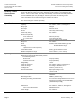
Flowrite VF599 Series Three-Way Valves 2-1/2 to 6-inch Flanged Iron Body Technical Instructions Document Number 155-160P25 June 14, 2019 Accessories Figure 1. Stem Heating Element. ASZ6.6 The stem heating element prevents the formation of ice on the stem when the medium temperature drops below 32°F (0°C). It is suited for universal use with valves having a stem or spindle diameter of 10 or 14 mm.
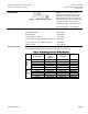
Technical Instructions Document Number 155-160P25 June 14, 2019 Service Flanges Flowrite VF599 Series Three-Way Valves 2-1/2 to 6-inch Flanged Iron Body Table 3. Part Numbers for VF 599 Service Flanges. Line Size Service Flange Part Numbers Inches (mm) ANSI Class 125 ANSI Class 250 Flange Gasket and Bolt Kits 2-1/2 (65) 599-05011 599-05016 3 (80) 599-05012 599-05017 4 (100) 599-05013 599-05018 5(125) 599-05014 599-05019 6 (150) 599-05015 599-05020 Table 4.
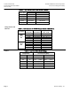
Flowrite VF599 Series Three-Way Valves 2-1/2 to 6-inch Flanged Iron Body Technical Instructions Document Number 155-160P25 June 14, 2019 Table 6. Maximum Water Capacity - U.S. Gallons Per Minute. Flow is Equal Through Both Ports.
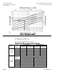
Technical Instructions Document Number 155-160P25 June 14, 2019 Flowrite VF599 Series Three-Way Valves 2-1/2 to 6-inch Flanged Iron Body Figure 2. Water Capacity Graph. Selection Example Select a valve given: 1 = Required flow = 500 gpm 2 = Desired pressure drop = 5 psi 3 = Select a 5-inch (125 mm) valve, Cv 250. Table 9. Close-off Pressures for Pneumatic Actuators.
Flowrite VF599 Series Three-Way Valves 2-1/2 to 6-inch Flanged Iron Body Technical Instructions Document Number 155-160P25 June 14, 2019 Figure 3. Close-off Pressures. Operation This Flowrite three-way valve is designed as a mixing valve. As the valve stem moves downward, the flow through the NO port decreases and the flow through the NC port increases. As the valve stem moves upward, the flow through the NO port increases and the flow through the NC port decreases.
Technical Instructions Document Number 155-160P25 June 14, 2019 Sizing Flowrite VF599 Series Three-Way Valves 2-1/2 to 6-inch Flanged Iron Body The sizing of a valve is important for correct system operation. An undersized valve will not have sufficient capacity at maximum load. An oversized valve may initiate cycling and the seat and throttling plug can be damaged because of the restricted opening.
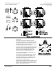
Flowrite VF599 Series Three-Way Valves 2-1/2 to 6-inch Flanged Iron Body Dimensions Technical Instructions Document Number 155-160P25 June 14, 2019 The letters in Figure 5 refer to actuator and service envelope dimensions in Table 11. See Table 12 for valve body dimensions. Table 11. Dimensions of the Actuator and Recommended Service Envelope. Dimensions in Inches (Millimeters). Actuator 8" Pneumatic 12" Pneumatic SKB/C with handle closed Figure 5.
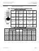
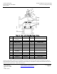
Technical Instructions Document Number 155-160P25 June 14, 2019 Flowrite VF599 Series Three-Way Valves 2-1/2 to 6-inch Flanged Iron Body Parts List Table 13. Parts List for Three-Way Flanged Valves.