
Installation Instructions

Installation Instructions
Document No. 129-458
February 25, 2013
599 Series Ball Valve Assembly
Weather Shield
Item Number 129-458, Rev. AA
Page 1 of 2
Product Description
The 599 Series Ball Valve Assembly Weather Shield
provides additional protection against the elements
for actuators in outdoor installations. The cover is
easy to install, with all necessary hardware included
in the assembly kit.
NOTES:
• This unit is approved for outdoor installation
only when a weatherproof conduit connector
is used.
• The weather shield provides NEMA 3R
protection against rain, sleet and damage
from external ice formation when installed in
the orientation shown in
Figure 2.
Contents
1 - Weather shield, bottom (with opening for valve)
1 - Weather shield, top
4 - UV resistant cable ties
4 – Retention screws
Product Number
599-10080
Caution Notation
CAUTION:
Equipment damage or loss
of data may occur if you do
not follow procedures as
specified.
Required Tools
• Conduit knockout punch
• No. 1 Phillips Screwdriver
Expected Installation Time
15 minutes
Installation
For 1/2" through 1-1/2" Ball Valves
NOTE: For 2" Ball Valves and existing installations,
see Retrofit Installations
1. Using a conduit knockout punch, make a hole
through the weather shield at the preferred
conduit location.
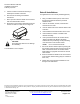
2. Insert valve through the opening in the bottom
half of the weather shield. See Figure 1.
Figure 1.
3. Rest the ball valve bracket and actuator
assembly between the four positioning screws
protruding from the bottom of the weather shield.
4. Secure the weather shield in place by driving the
four weather shield retention screws fully into the
sides of the bottom half of the weather shield
while holding it up against the bottom of the ball
valve bracket. See
Figure 1.
NOTE: The actuator and weather shield must
be mounted vertically to ensure
NEMA 3R rating. See
Figure 2.
Figure 2. Acceptable Mounting Position.