
Data Sheet for Product

Technical Instructions 599 Series 6-Way Ball Valves
Document Number 155-803
November 10, 2020
Page 6 Siemens Industry, Inc.
Operation
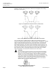
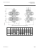
The 6-way ball valve enables control between two sources (A and B) through
positions 0° and 90° and is closed at 45°. Both sources supply the same coil (C).
See Figure 2 and Figure 3.
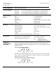
Figure 2. 6-way Ball Valve Characteristic Curve, 1/2-Inch Valve.
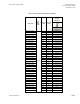
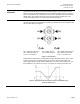
Figure 3. 6-way Ball Valve Characteristic Curve, 3/4- and 1-inchValves.
The 6-way ball valve is combined with the GDE161.1P modulating fail-in-place
actuator. The market standard operation is shown in Figure 2 and Figure 3. A control
signal of 0V provides full flow from Source A, 5V is both Source A and Source B
closed, and 10V provides full flow from Source B. Both Sources A and B have a
linear flow characteristic. The control range for modulating the flow of Source A is
with a control signal between 0V and 3.3V for the 1/2-inch valves and between 0V
and 4.5V for the 3/4-inch and 1-inch valves. The control range for modulating the
flow of Source B is with a control signal between 6.6V and 10V for the 1/2-inch
valves and between 5.5V and 10V for the 3/4-inch and 1-inch valves.
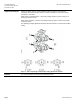
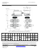
CAUTION:
For the actuator to operate according to the market standard described
above, the DIP switches must be set as shown in Figure 4. The left DIP
switch is set to the off (down) position, while the middle and right DIP
switches are set to the on (up) position. These are the settings when the
171C 6-way valve/actuator assemblies are shipped from the factory. If the
GDE161.1P actuator is purchased separately, the default DIP switch
settings are all in the off (down) position, and must be set as shown in
Figure 4 when used with the 6-way ball valves.
Figure 4. GDE161.1P DIP Switch Settings for
Proper 6-Way Ball Valve Operation.