
User Guide


Powermite Two-Way Flared Valves Normally Open/Normally Closed Technical Instructions
155-311P25
March 7, 2005
Siemens Industry, Inc. Page 5
Installation
In concealed installations, allow 2 inches (50 mm) from the top of the actuator to
remove the upper housing for valve servicing.
Install all valves so that the flow is directed under the valve seat. Flow direction arrows
are cast on the valve body.
Never use the valve housing as a lever arm to tighten the body when taking up on a
thread.
The preferred installation position is upright. Install the valve in any position except
upside down.
Rotate the valve top to allow piping the control air from a convenient position.
Install hand valves on the supply and return piping to allow for servicing.
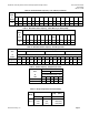
Dimensions
Figure 2. Normally Open. Figure 3. Normally Closed.
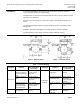
Table 7. Troubleshooting.
Complaint Problem Recommended
Correction
Complaint Problem Recommended
Correction
Valve Noise
Excessive fluid
velocity in piping or
excessive pressure
drop
Reduce pressure
drop or change
valve size
Inadequate
Close-off
Insufficient control
air pressure
Raise control air
pressure
Improper direction
flow
Re-pipe valve for
flow as stamped on
valve body
Excessive pressure
drop across valve
Reduce system
differential or in-
crease control air
pressure
Flashing because of
low system pres-
sure or excessive
fluid temperature
Basic system
problem cannot be
corrected within
valve
Foreign material in
valve
Flush system or
clean out foreign
matter
Fluid leaks
Damaged valve or
worn packing
Replace valve or
packing
Damaged or worn
valve disc or
diaphragm
Replace disc or
diaphragm