
User Manual

LOGO! installation and wiring
2.2 Installing/removing LOGO!
LOGO!
Manual, 04/2011, A5E03556174-01
41
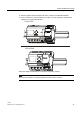
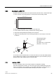
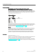
5. Slide the digital module towards the left until it contacts the LOGO! Base Module.
6. Using a screwdriver, push the interlock to the left. In its end position the slide interlock
engages in the LOGO! Base Module.
/2*2%$
/2*2%$
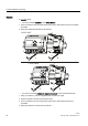
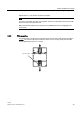
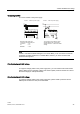
Repeat the digital module steps to mount further expansion modules.
Note
The expansion interface on the last expansion module must be covered.