
User Manual


LOGO! installation and wiring
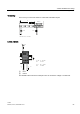
2.3 Wiring LOGO!
LOGO!
58 Manual, 04/2011, A5E03556174-01
2.3.5 Connecting the EIB bus
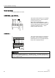
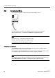
The connection is carried out via the two-pole screw terminal (+ and -).
5816723
%86
(,%
3URJൻ
Only the red-black core pair is used, the white-yellow core pair is not connected.
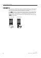
Press the button "Prog ↓" to switch the CM EIB/KNX to programming mode.
Note
The button "Prog ↓ " should not be pressed too firmly.
If the bus connection is OK, the LED lights up green.
In programming mode, the LED lights up orange.
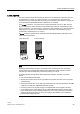
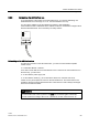
Networking on the EIB bus
The CM EIB/KNX takes over the communication between LOGO! and
EIB
and makes
communication available via
EIB
inputs/outputs.
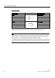
The application of the CM EIB/KNX fills the complete LOGO! process image; that is, inputs
or outputs which are not occupied on LOGO! can be occupied on the EIB.
Note
For detailed information about the networking of LOGO! on the
EIB
bus please refer to the
LOGO! CM EIB/KNX documentation, in particular the Micro Automation Set 8.