
User Manual


Easy to create the device configuration
5.5 Configuring the operation of the CPU and modules
Easy Book
Manual, 03/2014, A5E02486774-AF
79
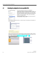
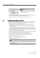
Table 5- 3 Clock memory
Bit number
7
6
5
4
3
2
1
0
Tag name
Period (s)
2.0
1.6
1.0
0.8
0.5
0.4
0.2
0.1
Frequency (Hz)
0.5
0.625
1
1.25
2
2.5
5
10
Because clock memory runs asynchronously to the CPU cycle, the status of the clock memory can change s
everal times
during a long cycle.
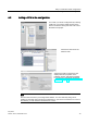
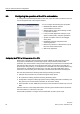
Configuring the operation of the I/O and communication modules
To configure the operational parameters for the signal module (SM), signal board (SB), or
communication module (CM), select the module in the Device view and use the "Properties"
tab of the inspector window.
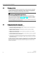
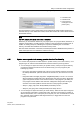
Signal module (SM) and signal board (SB)
•
Digital I/O: Configure the individual inputs, such as
for Edge detection and "pulse catch" (to stay on or
off for one scan after a momentary high- or low
pulse). Configure the outputs to use a freeze or
substitute value on a transition from RUN mode to
STOP mode.
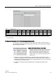
● Analog I/O: Configure the parameters for individual inputs (such as voltage / current,
range and smoothing) and also enable underflow or overflow diagnostics. Configure the
parameters for individual analog outputs and enable diagnostics, such as short-circuit (for
voltage outputs) or overflow values.
● I/O addresses: Configure the start address for the set of inputs and outputs of the
module.