
User Manual

Programming made easy
6.6 High-speed counter (HSC)
Easy Book
122 Manual, 03/2014, A5E02486774-AF
Input addresses for the HSC
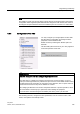
When you configure the CPU, you have the option to enable and configure the "Hardware
inputs" for each HSC.
All HSC inputs must be connected to terminals on the CPU module or optional signal board
that plugs into the front of the CPU module.
Note
As shown in the following tables, the default assignments for the optional signals for the
different HSCs overlap. For example, the optional external reset for HSC 1 uses the same
input as one of the inputs for H
SC 2. For
For V4 CPUs or later, you can reassign the HSC inputs during the CPU configuration. You
do not have to use the default input assignments.
Always ensure that you have configured your HSCs so that any one input is not
being used
by two HSCs.
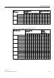
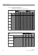
The following tables show the HSC input default assignments for the on-board I/O of CPUs
and an optional SB. (If the SB model selected has only 2 inputs, only 4.0 and 4.1 inputs are
available.)
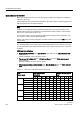
HSC input table definitions
●
Single-phase:
C is Clock
input,
[d]
is direction
input (optional), and
[R]
is external reset
input (optional)
(Reset is available only for "Counting" mode.)
●
Two-phase:
CU
is Clock Up
input,
CD
is Clock Down
input, and
[R]
is external reset
input.(optional)
(Reset is available only for "Counting" mode.)
●
AB-phase quadrature:
A is the Clock A
input,
B
is the Clock B
input, and
[R]
is external
reset
input (optional)
.
(Reset is available only for "Counting" mode.)
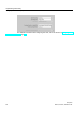
Table 6- 31 CPU 1211C: HSC default address assignments
HSC
counter mode
CPU on-board input
(default 0.x)
Optional SB input (default
4.x)
1
0
1
2
3
4
5
0
1
2
3
HSC 1
1-phase
C
[d]
[R]
C
[d]
[R]
2-phase
CU
CD
[R]
CU
CD
[R]
AB-phase
A
B
[R]
A
B
[R]
HSC 2
1-phase
[R]
C
[d]
[R]
C
[d]
2-phase
[R]
CU
CD
[R]
CU
CD
AB-phase
[R]
A
B
[R]
A
B
HSC 3 1-phase C [d] C [d] R]
2-phase
AB-phase
HSC4
1-phase
C
[d]
C
[d]
R]
2-phase
CU
CD