
User Manual


PID is easy
8.6 Configuring the PID controller
Easy Book
Manual, 03/2014, A5E02486774-AF
189
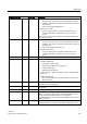
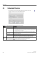
Table 8- 10 Sample configuration settings for the PID_3Step instruction
Settings
Description
Basic
Controller type
Selects the engineering units.
Invert the control logic Allows selection of a reverse-acting PID loop.
• If not selected, the PID loop is in direct-acting mode, and the output of PID loop
increases if the input value < setpoint).
• If selected, the output of the PID loop increases if the input value > setpoint.
Activate mode after
CPU restart
Restarts the PID loop after it is reset or if an input limit has been exceeded and
returned to the valid range.
Set Mode to: Defines the mode that the user wants the PID to go to after restart.
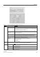
Input Selects either the Input parameter or the Input_PER parameter (for analog) for the
process value. Input_PER can come directly from an analog input module.
Output Selects either to use the digital outputs (Output_UP and Output_DN) or to use the
analog output (Output_PER) for the output value.
Feedback Selects the type of device status returned to the PID loop:
• No feedback (default)
• Feedback
• Feedback_PER
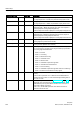
Process
value
Scales both the range and the limits for the process value. If the process value goes below the low limit or
above the high limit, the PID loop goes to inactive mode and sets the output value to 0.
To use Input_PER, you must scale the analog process value (input value).
Actuator Motor transition
time
Sets the time from open to close for the valve. (Locate this value on the data sheet or
the faceplate of the valve.)
Minimum ON time Sets the minimum movement time for the valve. (Locate this value on the data sheet or
the faceplate of the valve.)
Minimum OFF
time
Sets the minimum pause time for the valve. (Locate this value on the data sheet or the
faceplate of the valve.)