
User Manual


Technical specifications
A.4 Specifications for the digital inputs and outputs
Easy Book
Manual, 03/2014, A5E02486774-AF
303
Note
When switching frequencies above 20
KHz, it is important that the digital inputs receive a
square wave. Consider the following options to improve the signal quality to the inputs:
•
Minimize the cable length
•
Change a driver from a sink only driver to a sinking and sourcing driver
•
Change to a higher quality cable
•
Reduce the circuit/components from 24 V to 5 V
•
Add an external load at the input
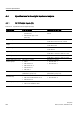
Table A- 26 HSC clock input rates (max.)
Technical data
Single phase
Quadrature phase
CPU 1211C
100 KHz
80 KHz
CPU 1212C 100 KHz (Ia.0 to Ia.5) and
30 KHz (Ia.6 to Ia.7)
80 KHz (Ia.0 to Ia.5) and
20 KHz (Ia.6 to Ia.7)
CPU 1214C, CPU 1215C 100 KHz (Ia.0 to Ia.5) and
30 KHz (Ia.6 to Ib.5)
80 KHz (Ia.0 to Ia.5) and
20 KHz (Ia.6 to Ib.5)
CPU 1217C
1 MHz (DIb.2 to DIb.5)
1 MHz (DIb.2 to DIb.5)
High-speed (200 KHz) SB
200 kHz
160 kHz
Standard-speed SB
30 kHz
20 kHz
1
Logic 1 level = 15 to 26 VDC
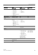
A.4.2
120/230 VAC digital AC inputs
Table A- 27 120/230 VAC digital inputs
Technical data
SM
Type
IEC Type 1
Rated voltage
120 VAC at 6 mA, 230 VAC at 9 mA
Continuous permissible voltage
264 VAC
Surge voltage
N/A
Logic 1 signal (min.)
79 VAC at 2.5 mA
Logic 0 signal (max.)
20 VAC at 1 mA
Leakage current (max.)
1 mA
Isolation (field side to logic)
1500 VAC for 1 minute
Isolation groups
1
4
Input delay times
• Typical: 0.2 to 12.8 ms, user selectable
• Maximum: --
Connection of 2 wire proximity sensor (Bero) (max.)
1 mA