
User Manual

Easy to communicate between devices
7.10 PtP, USS, and Modbus communication protocols
Easy Book
164 Manual, 03/2014, A5E02486774-AF
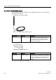
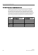
The serial communication interfaces have the following characteristics:
● Have an isolated port
● Support Point-to-Point protocols
● Are configured and programmed through the point-to-point communication processor
instructions
● Display transmit and receive activity by means of LEDs
● Display a diagnostic LED (CMs only)
● Are powered by the CPU: No external power connection is needed.
Refer to the technical specifications for communication interfaces.
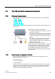
LED indicators
The communication modules have three LED indicators:
● Diagnostic LED (DIAG): This LED flashes red until it is addressed by the CPU. After the
CPU powers up, it checks for CMs and addresses them. The diagnostic LED begins to
flash green. This means that the CPU has addressed the CM, but has not yet provided
the configuration to it. The CPU downloads the configuration to the configured CMs when
the program is downloaded to the CPU. After a download to the CPU, the diagnostic LED
on the communication module should be a steady green.
● Transmit LED (Tx): The transmit LED illuminates when data is being transmitted out the
communication port.
● Receive LED (Rx): This LED illuminates when data is being received by the
communication port.
The communication board provides transmit (TxD) and receive (RxD) LEDs. It has no
diagnostic LED.
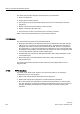
7.10.3
PtP instructions
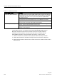
The PORT_CFG, SEND_CFG, and RCV_CFG instructions allow you to change the
configuration from your user program.
● PORT_CFG changes the port parameters such as baud rate.
● SEND_CFG changes the configuration of serial transmission parameters.
● RCV_CFG changes the configuration of serial receiver parameters in a communication
port. This instruction configures the conditions that signal the start and end of a received
message. Messages that satisfy these conditions will be received by the RCV_PTP
instruction.