
User Manual
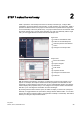

Introducing the powerful and flexible S7-1200
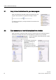
1.5 Mounting dimensions and clearance requirements
Easy Book
24 Manual, 03/2014, A5E02486774-AF
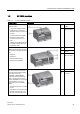
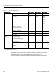
Table 1- 9 Mounting dimensions (mm)
S7-1200 Devices
Width A (mm)
Width B (mm)
Width C (mm)
CPU
CPU 1211C and CPU 1212C
90
45
--
CPU 1214C
110
55
--
CPU 1215C 130 65 (top) Bottom:
C1: 32.5
C2: 65
C3: 32.5
CPU 1217C 150 75 Bottom:
C1: 37.5
C2: 75
C3: 37.5
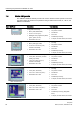
Signal modules Digital 8 and 16 point
Analog 2, 4, and 8 point
Thermocouple 4 and 8 point
RTD 4 point
SM 1278 IO Link-Master
45 22.5 --
Digital DQ 8 x Relay (Changeover)
70
35
--
Analog 16 point
RTD 8 point
70 35 --
Communication
interfaces
CM 1241 RS232, and
CM 1241 RS422/485
CM 1243-5 PROFIBUS master and
CM 1242-5 PROFIBUS slave
CM 1242-2 AS-i Master
CP 1242-7 GPRS
30 15 --
TS (Teleservice) Adapter IE Basic
1
TS Adapter
TS Module
30
30
15
15
--
--
1
Before installing the TS (Teleservice) Adapter IE Basic, you must first connect the TS Adapter and a TS module. The
total width ("width A") is 60 mm.
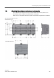
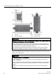
Each CPU, SM, CM, and CP supports mounting on either a DIN rail or on a panel. Use the
DIN rail clips on the module to secure the device on the rail. These clips also snap into an
extended position to provide screw mounting positions to mount the unit directly on a panel.
The interior dimension of the hole for the DIN clips on the device is 4.3 mm.
A 25 mm thermal zone must be provided above and below the unit for free air circulation.