
User Manual


Motion control is easy
10.6 Operation of motion control for S7-1200
Easy Book
Manual, 03/2014, A5E02486774-AF
249
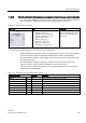
10.6.3.2
Configuration of homing parameters
Configure the parameters for active and passive homing in the "Homing" configuration
window. The homing method is set using the "Mode" input parameter of the motion control
instruction. Here, Mode = 2 means passive homing and Mode = 3 means active homing.
Note
Use one of the following measures to ensure that the machine does not travel to a
mechanical endstop in the event of a direction reversal:
•
Keep the approach velocity low
•
Increase the configured acceleration/deceleration
•
Increase the distance between hardware limit switch and mechanical stop
Table 10- 37 Configuration parameters for homing the axis
Parameter
Description
Input reference point switch
(Active and passive homing)
Select the digital input for the reference point switch from the drop-down list box. The
input must be interrupt-capable. The onboard CPU inputs and inputs of an inserted
signal board can be selected as inputs for the reference point switch.
The default filter time for the digital inputs is 6.4 ms. When the digital inputs are used
as a reference point switch, this can result in undesired decelerations and thus
inaccuracies. Depending on the reduced velocity and extent of the reference point
switch, the reference point may not be detected. The filter time can be set under
"Input filter" in the device configuration of the digital inputs.
The specified filter time must be less than the duration of the input signal at the
reference point switch.
Auto reverse after reaching the
hardware limit switches
(Active homing only)
Activate the check box to use the hardware limit switch as a reversing cam for the
reference point approach. The hardware limit switches must be configured and
activated for direction reversal.
If the hardware limit switch is reached during active homing, the axis brakes at the
configured deceleration (not with the emergency deceleration) and reverses direction.
The reference point switch is then sensed in reverse direction.
If the direction reversal is not active and the axis reaches the hardware limit switch
during active homing, the reference point approach is aborted with an error and the
axis is braked at the emergency deceleration.
Approach direction
(Active and passive homing)
With the direction selection, you determine the "approach direction" used during
active homing to search for the reference point switch, as well as the homing
direction. The homing direction specifies the travel direction the axis uses to
approach the configured side of the reference point switch to carry out the homing
operation.