
User Manual

Technical specifications
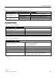
A.1 General technical specifications
Easy Book
Manual, 03/2014, A5E02486774-AF
287
Reverse voltage protection
Reverse voltage protection circuitry is provided on each terminal pair of +24 VDC power or
user input power for CPUs, signal modules (SMs), and signal boards (SBs). It is still possible
to damage the system by wiring different terminal pairs in opposite polarities.
Some of the 24 VDC power input ports in the S7-1200 system are interconnected, with a
common logic circuit connecting multiple M terminals. For example, the following circuits are
interconnected when designated as "not isolated" in the data sheets: the 24 VDC power
supply of the CPU, the sensor power of the CPU, the power input for the relay coil of an SM,
and the power supply for a non-isolated analog input. All non-isolated M terminals must
connect to the same external reference potential.
WARNING
Connecting non-isolated M terminals to different reference potentials will cause unintended
current flows that may cause damage or unpredictable operation in the PLC and any
connected equipment.
Failure to comply with these guidelines could cause damage or unpredictable operation
which could result in death or severe personal injury and/or property damage.
Always ensure that all non-isolated M terminals in an S7-1200 system are connected to the
same reference potential.
DC Outputs
Short -ircuit protection circuitry is not provided for DC outputs on CPUs, signal modules
(SMs) and signal boards (SBs).
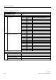
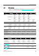
Relay electrical service life
The typical performance data estimated from sample tests is shown below. Actual
performance may vary depending upon your specific application. An external protection
circuit that is adapted to the load will enhance the service life of the contacts. N.C. contacts
have a typical service life of about one-third that of the N.O. contact under inductive and
lamp load conditions.
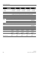
An external protective circuit will increase the service life of the contacts.