
User Manual


Technical specifications
A.2 CPU modules
Easy Book
292 Manual, 03/2014, A5E02486774-AF
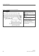
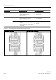
Table A- 12 Wiring diagram for CPU 1214C AC/DC/Relay
CPU 1214C AC/DC/Relay
①
24 VDC Sensor Power Out. For
additional noise immunity, connect "M"
to chassis ground even if not using
sensor supply.
②
For sinking inputs, connect "-" to "M"
(shown). For sourcing inputs, connect
"+" to "M".
Note 1: X11 connectors must be gold. See
the S7-1200 System Manual, Appendix C,
Spare Parts for order number.
Note 2: Either the L1 or N (L2) terminal can
be connected to a voltage source up to
240 VAC. The N terminal can be
considered L2 and is not required to be
grounded. No polarization is required for L1
and N (L2) terminals.