
User Manual

Technical specifications
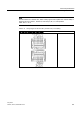
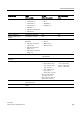
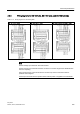
A.4 Specifications for the digital inputs and outputs
Easy Book
304 Manual, 03/2014, A5E02486774-AF
Technical data
SM
Cable length
Unshielded
300 meters
Shielded
500 meters
Number of inputs on simultaneously
8
1
Channels within a group must be of the same phase.
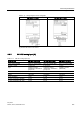
A.4.3
Digital outputs (DQ)
Table A- 28 Specifications for the digital outputs (DQ)
Technical data
Relay
(CPU and SM)
24 VDC
(CPU, SM, and SB)
200 KHZ 24 VDC
(SB)
Type Relay, dry contact Solid state - MOSFET
(Source)
Solid state - MOSFET
(Sink/Source)
Voltage range 5 to 30 VDC or
5 to 250 VAC
20.4 to 28.8 VDC 20.4 to 28.8 VDC
1
4.25 to 6.0 VDC
2
Logic 1 signal at max. current N/A 20 VDC min. L+ minus 1.5 V
1
L+ minus 0.7 V
2
Logic 0 signal with 10 KΩ load N/A CPU: 20 VDC min.,
0.1 VDC max.
SB: 0.1 VDC max.
SM DC: 0.1 VDC max.
1.0 VDC, max.
1
0.2 VDC, max.
2
Current (max.) 2.0 A 0.5 A 0.1 A
Lamp load 30 W DC / 200 W AC SB: 5 W N/A
ON state resistance
0.2 Ω max. when new
0.6 Ω max.
11 Ω max.
1
or 7 Ω max.
2
OFF state resistance N/A N/A 6 Ω max.
1
or 0.2 Ω max.
2
Leakage current per point
N/A
10 μA max.
N/A
Pulse Train Output rate CPU: N/A
3
CPU: 100 KHz max.,2 Hz
min.
4
SB: 20 KHz max., 2 Hz min.
5
200 kHz max., 2 Hz min.
Surge current 7 A with contacts closed CPU: 8 A for 100 ms max.
SB: 5 A for 100 ms max.
SM: 8 A for 100 ms max.
0.11 A
Overload protection
No
No
No
Isolation (field side to logic) Coil to contact: 1500 VAC
for 1 minute
Coil to logic: None
500 VAC for 1 minute 500 VAC for 1 minute