
User Manual

Technical specifications
A.8 RTD and Thermocouple modules
Easy Book
318 Manual, 03/2014, A5E02486774-AF
Note
After power is applied, the module performs internal calib
ration for the analog-to-digital
converter. During this time the module reports a value of 32767 on each channel until valid
data is available on that channel. Your user program may need to allow for this initialization
time. Because the configuration of t
he module can vary the length of the initialization time,
you should verify the behavior of the module in your configuration. If required, you can
include logic in your user program to accommodate the initialization time of the module.
A.8.1
SB 1231 RTD and SB 1231 TC specifications
Note
To use these TC and RTD SBs, your CPU firmware must be V2.0 or higher.
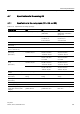
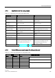
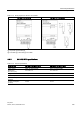
Table A- 47 General specifications
Technical data
SB 1231 AI 1 x16 bit TC
SB 1231 AI 1 x 16 bit RTD
Order number
6ES7 231-5QA30-0XB0
6ES7 231-5PA30-0XB0
Dimensions W x H x D (mm)
38 x 62 x 21 mm
38 x 62 x 21 mm
Weight
35 grams
35 grams
Power dissipation
0.5 W
0.7 W
Current consumption (SM Bus)
5 mA
5 mA
Current consumption (24 VDC)
20 mA
25 mA
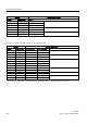
Number of inputs (Page 323)
Type
1
Floating TC and mV
1
Module-referenced RTD and Ω
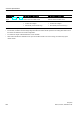
Diagnostics
• Overflow / underflow
1, 2
• Wire break
3
• Overflow / underflow
1, 2
• Wire break
3
1
The overflow and underflow diagnostic alarm information will be reported in the analog data values even if the alarms
are disabled in the module configuration.
2
RTD: For resistance ranges, underflow detection is never enabled.
3
When wire break alarm is disabled and an open wire condition exists in the sensor wiring, the module may report
random values.