SIMATIC IOT2020, SIMATIC IOT2040 ___________________ Preface 1 ___________________ Overview SIMATIC SIMATIC IOT SIMATIC IOT2020, SIMATIC IOT2040 Operating Instructions 2 ___________________ Safety instructions Installing and connecting the 3 ___________________ device 4 ___________________ Software and commissioning 5 ___________________ Expand device Maintaining and repairing the 6 ___________________ device ___________________ 7 Technical specifications ___________________ A Technical support ________
Legal information Warning notice system This manual contains notices you have to observe in order to ensure your personal safety, as well as to prevent damage to property. The notices referring to your personal safety are highlighted in the manual by a safety alert symbol, notices referring only to property damage have no safety alert symbol. These notices shown below are graded according to the degree of danger.
Preface These operating instructions contain all the information you need for commissioning and operation of a device in the SIMATIC IOT2000 family. It is intended both for programming and testing personnel who commission the device and connect it with other units (automation systems, programming devices), as well as for service and maintenance personnel who install add-ons or carry out fault/error analyses.
Preface Figures This manual contains figures of the described devices. The supplied device may differ in some details from the figures. Within some of the figures, one device is used to represent all devices.
Table of contents Preface ................................................................................................................................................... 3 1 2 3 Overview................................................................................................................................................. 7 1.1 Product description ................................................................................................................... 7 1.2 1.2.1 1.2.
Table of contents 7 A Technical specifications ........................................................................................................................ 39 7.1 Certificates and approvals ..................................................................................................... 39 7.2 7.2.1 7.2.2 Directives and declarations .................................................................................................... 41 Notes on CE marking ...............................
1 Overview 1.1 Product description The devices of the SIMATIC IOT family offer a robust, compact and flexible solution with a focus on the IOT environment and round off the SIMATIC IPC product range in the lower output range.
Overview 1.
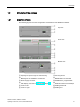
Overview 1.2 Structure of the devices 1.2 Structure of the devices 1.2.1 SIMATIC IOT2020 The following figures show the configuration and interfaces of the SIMATIC IOT2020.
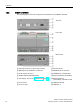
Overview 1.3 Accessories 1.2.2 SIMATIC IOT2040 The following figures show the configuration and interfaces of the SIMATIC IOT2040.
Overview 1.3 Accessories 1.3 Accessories This chapter contains the scope of accessories valid at the time these operating instructions were written. The following accessories are not included in the scope of delivery and can be ordered separately. Additional accessories can be found on the Internet at: Industry Mall (https://mall.industry.siemens.
Overview 1.
Safety instructions 2.1 2 General safety instructions WARNING Life-threatening voltages are present with an open control cabinet When you install the device in a control cabinet, some areas or components in the open control cabinet may be carrying life-threatening voltages. If you touch these areas or components, you may be killed by electric shock. Switch off the power supply to the cabinet before opening it.
Safety instructions 2.1 General safety instructions NOTICE Use in the scope of application for the UL61010-2-201 When the device is used in the area of Industrial Control Equipment in accordance with UL61010-2-201, note that the device is classified as "Open Type". A UL61010-2-201 conform enclosure is therefore a mandatory requirement for approval or operation according to UL61010-2-201.
Safety instructions 2.1 General safety instructions Battery and rechargeable battery WARNING Risk of explosion and release of harmful substances Improper handling of lithium batteries can result in an explosion of the batteries. Explosion of the batteries and the released pollutants can cause severe physical injury. Worn batteries jeopardize the function of the device.
Safety instructions 2.1 General safety instructions Industrial Security Siemens provides products and solutions with industrial security functions that support the secure operation of plants, systems, machines and networks. In order to protect plants, systems, machines and networks against cyber threats, it is necessary to implement – and continuously maintain – a holistic, state-of-the-art industrial security concept. Siemens’ products and solutions only form one element of such a concept.
Safety instructions 2.2 Notes on use 2.2 Notes on use NOTICE Possible functional restrictions in case of non-validated plant operation The device is tested and certified on the basis of the technical standards. In rare cases, functional restrictions can occur during plant operation. Validate the correct functioning of the plant to avoid functional restrictions.
Safety instructions 2.
Installing and connecting the device 3.1 Preparing for installation 3.1.1 Checking the delivery 3 Procedure 1. When accepting a delivery, please check the packaging for visible transport damage. 2. If any transport damage is present at the time of delivery, lodge a complaint at the shipping company in charge. Have the shipper confirm the transport damage immediately. 3. Unpack the device at its installation location. 4. Keep the original packaging in case you have to transport the unit again.
Installing and connecting the device 3.1 Preparing for installation 6. If the contents of the packaging are incomplete, damaged or do not match your order, inform the responsible delivery service immediately. WARNING Electric shock and fire hazard due to damaged device A damaged device can be under hazardous voltage and trigger a fire in the machine or plant. A damaged device has unpredictable properties and states. Death or serious injury could occur.
Installing and connecting the device 3.1 Preparing for installation 3.1.2 Identification data of the device The device can be clearly identified with the help of this identification data in case of repairs or theft. You can find this information on the rating plate. The following illustration shows an example. Example rating plate: Enter the identification data in the table below: Order number 6ES ... Serial number S VP Production version FS All existing Ethernet addresses (MAC) 3.1.
Installing and connecting the device 3.2 Mounting the device Clearances Ensure that the following clearances measurements to another component or to a wall of a housing are complied with: ● Below the device: ≥ 50 mm ● Above the device: ≥ 50 mm 3.2 Mounting the device 3.2.1 Mounting instructions Note the following: ● The device is approved for operation in closed rooms only. ● For installation in a cabinet, observe the SIMATIC setup guidelines (http://support.automation.siemens.
Installing and connecting the device 3.2 Mounting the device Fasten securely NOTICE Insufficient load carrying capacity If the mounting surface for wall mounting does not have a sufficient load-bearing capacity, the device may fall and be damaged. Ensure that the mounting surface on the wall can bear four times the total weight of the device, including fixing elements.
Installing and connecting the device 3.2 Mounting the device 3.2.2 Mounting on DIN rails Requirement ● A DIN rail, 35 mm standard profile The DIN rail is installed at the installation site. Procedure Mounting 1. Place the device and rail clip on the upper edge of the standard profile rail at the position shown and push the device down. 2. Swing the rail clips of the device from below via the standard profile rail. 3. Push the device in the direction of the standard profile rail.
Installing and connecting the device 3.2 Mounting the device 3.2.3 Wall mounting The device is suitable for horizontal or vertical wall mounting. Requirement ● Four push-in lugs The push-in lugs must be ordered separately, see section "Accessories (Page 11)" ● Four anchors and four screws Procedure for mounting 1. Guide a push-in lug through the corresponding opening at the top of the device, as shown 2. Press the push-in lug down. 3.
Installing and connecting the device 3.3 Connecting the device 3.3 Connecting the device 3.3.1 Notes on connecting WARNING Risk of lightning strikes A lightning flash may enter the mains cables and data transmission cables and jump to a person. Death, serious injury and burns can be caused by lightning. Take the following precautions: • Disconnect the device from the power supply in good time when a thunderstorm is approaching.
Installing and connecting the device 3.3 Connecting the device 3.3.2 Connecting the power supply Note The device should only be connected to a 9...36 V DC power supply which meets the requirements of safe extra low voltage (SELV) according to IEC/EN/DIN EN/UL 60950-1. The power supply must meet the requirement NEC Class 2 or LPS according to IEC/EN/DIN EN/UL 60950-1. Note The power supply must be adapted to the input data of the device, see chapter "General technical specifications (Page 45)".
Installing and connecting the device 3.3 Connecting the device 3.3.3 Securing the cables Use cable ties or cable clamps to secure the connected cables to suitable fixing elements for strain relief. Make sure that the cables are not crushed by the cable tie or the cable clamps.
Software and commissioning 4 Operating system and software for the SIMATIC IOT devices are freely programmable and are downloaded from the Micro SD card when the device is booted. For SIMATIC IOT2040: The device starts with "Secure Boot", which means the SD card with the customer-specific image must be signed accordingly. Additional information on the topics software, "Secure Boot", commissioning and Micro SD image is available in the SIMATIC IOT2000 Forum.
Software and commissioning SIMATIC IOT2020, SIMATIC IOT2040 30 Operating Instructions, 10/2016, A5E37656492-AB
Expand device 5.1 5 Insert Micro SD card Requirement ● The device is disconnected from the power supply. ● Micro SD card that is suitable for industrial use. Procedure Installation NOTICE Inserting a memory card If you are using the Micro SD card in a device installed in a system, you must observe the safety regulations for work on electrical systems. Carefully insert the Micro SD card into the Micro SD holder without applying excess force. 1. Open the cover on the right. 2.
Expand device 5.2 Install Arduino shield 5.2 Install Arduino shield Requirement ● The device is disconnected from the power supply. ● An Arduino shield Procedure NOTICE Install Arduino shield Do not under any circumstances insert the Arduino shield incorrectly. Ensure that the contact pins of the Arduino shield connect correctly with the terminal strips of the motherboard. Arduino shield with operator control or display elements Some Arduino shields have operator control and display elements.
Expand device 5.3 Install Mini PCIe card Note Only use fixing elements made from plastic. You can use the four boreholes in the motherboard to additionally fasten the Arduino shield on the motherboard. Two of the boreholes are shown in the figure above. Use only fixing elements made from plastic, not metallic or conductive materials. 5.3 Install Mini PCIe card You can install a Mini PCIe card in a device of the type IOT2000.
Expand device 5.3 Install Mini PCIe card Procedure The following example describes the installation of a Mini PCIe WLAN card, including mounting of the antenna jacks. If you install a different Mini PCIe card, the work steps 4, 5 and 7 are not required. When the enclosure is secured with two screws at the rear panel, remove the two screws. Remove the battery, see section "Replace the backup battery (Page 36)". Then follow these steps: 1.
Maintaining and repairing the device 6.1 6 Maintenance To retain a high level of system availability, or devices with a back-up battery, we recommend the preventative replacement of the back-up battery at replacement intervals of 5 years. 6.2 Repair information Carrying out repairs Only qualified personnel are permitted to repair the device. Contact your local representative, see section "Service and support (Page 57)".
Maintaining and repairing the device 6.3 Replace the backup battery UL approval of the device only applies when the UL-approved components are used according to their "Conditions of Acceptability". We are not liable for functional limitations caused by the use of third-party devices or components. 6.3 Replace the backup battery This chapter applies to the device IOT2040, which has a back-up battery.
Maintaining and repairing the device 6.3 Replace the backup battery Requirement ● The device is disconnected from the power supply. ● A replacement battery with the article number A5E34345932 is available. Procedure NOTICE The time is lost after 30 seconds The time will be deleted if it takes you longer than 30 seconds to replace the battery. The device is no longer synchronous. Time-controlled programs will no longer run or will run at the wrong time. This may damage the plant.
Maintaining and repairing the device 6.4 Recycling and disposal 6.4 Recycling and disposal Marking according to WEEE guideline. Do not discard the device with your household waste. Observe the local legal guidelines for disposal. Alternatively, you can use a certified disposal service company.
Technical specifications 7.1 7 Certificates and approvals NOTICE The approvals are voided if certain modifications are made The device approvals are voided if the following modifications are made: • An Arduino shield or a Mini PCIe card was installed. • The enclosure was physically modified, for example, openings were created to make LEDs on a plug-in card in the device visible.
Technical specifications 7.1 Certificates and approvals FCC and Canada USA Federal Communications Commission Radio Frequency Interference Statement This equipment has been tested and found to comply with the limits for a Class A digital device, pursuant to Part 15 of the FCC Rules. These limits are designed to provide reasonable protection against harmful interference when the equipment is operated in a commercial environment.
Technical specifications 7.2 Directives and declarations 7.2 Directives and declarations 7.2.1 Notes on CE marking Electromagnetic compatibility This product meets the requirements of EU Directive 2014/30/EU "Electromagnetic Compatibility". The device is designed for the following areas of application corresponding to the CE marking: Scope of application Industrial area 7.2.
Technical specifications 7.2 Directives and declarations Charge Every person without a conductive connection to the electrical potential of his/her surroundings can be electrostatically charged. The material with which this person comes into contact is of particular significance. The figure shows the maximum electrostatic voltages with which a person is charged, depending on humidity and material. These values conform to the specifications of IEC 61000-4-2.
Technical specifications 7.2 Directives and declarations Protective measures against discharge of static electricity ● Disconnect the power supply before you install or remove modules which are sensitive to ESD. ● Pay attention to good grounding: – When handling electrostatical sensitive devices, make sure that persons, the workstation and devices, tools and packaging used are properly grounded. This way you avoid static discharge.
Technical specifications 7.3 Dimension drawings 7.3 Dimension drawings The following figures show the dimension drawings of the type IOT2000.
Technical specifications 7.4 Technical data 7.4 Technical data 7.4.1 General technical specifications General technical specifications 1 2 Article number See order documents Weight without mounting brackets • SIMATIC IOT2020: approx. 200 g • SIMATIC IOT2040: approx. 230 g Power supply 1 DC 9…36 V, no galvanic isolation Brief voltage interruption in accordance with Namur Up to 5 ms buffer time at 24 V DC and full load2 Max.
Technical specifications 7.4 Technical data Motherboard Processor RAM • SIMATIC IOT2020: Intel Quark X1000, 400 MHz • SIMATIC IOT2040: Intel Quark X1020, 400 MHz • SIMATIC IOT2020: 512 MB • SIMATIC IOT2040: 1 GB BIOS SPI Flash 8 MB Micro SD Slot for one Micro SD card Expansion slots 1 x Arduino shield 1 x mini PCIe for PCIe cards 30 x 50.59 mm or 30 x 26.8 mm via adapter Interfaces All devices of the type SIMATIC IOT2000 USB Type A, X60 USB 2.0 host, high current, max. 2.
Technical specifications 7.4 Technical data 7.4.2 Ambient conditions Climatic ambient conditions The temperature values have been checked in accordance with IEC 60068-2-1, IEC 60068-2-2 and IEC 60068-2-14. Permitted mounting positions, see section "Permitted mounting positions and mounting types (Page 21)“. Ambient temperature • Operation 0 … 50 °C * • Storage/transport -20 ... 70 °C Gradient • Operation Max.
Technical specifications 7.4 Technical data 7.4.3 Power demand of the components Maximum power consumption of the auxiliary components The information in the table below applies to the horizontal mounting position of the device at an ambient temperature of 50 °C. Auxiliary components Maximum permitted power consumption +5 V +3.3 V Maximum total power +1.5 V All components 6W3 Arduino shield 1 2 3 Permitted power distribution: Mini PCIe card -- 1.5 A USB 2.0 high current 500 mA -- 1 0.
Technical specifications 7.5 Hardware descriptions 7.5 Hardware descriptions 7.5.1 Motherboard The following figures show the motherboard of the SIMATIC IOT2040. The interfaces X30, X31 and X2 are not present in SIMATIC IOT2020.
Technical specifications 7.
Technical specifications 7.5 Hardware descriptions 7.5.2 External Interfaces 7.5.2.1 Power supply Plug connector, 2-pin Name of interface on the device: X80 7.5.2.2 Pin Assignment 1 GND (M) 2 +9...36 V DC (L+) USB USB socket type A Name of interface on the device: X60 Pin Assignment 1 +5 VDC, out (max.
Technical specifications 7.5 Hardware descriptions 7.5.2.
Technical specifications 7.
Technical specifications 7.5 Hardware descriptions 7.5.3 Internal interfaces 7.5.3.1 Arduino shield interfaces The tables below show the pin assignment of the interfaces of the Arduino shield, depending on the operating mode. The position of the interfaces and Pin 1 of the respective interface is available in section "Motherboard (Page 49)".
Technical specifications 7.5 Hardware descriptions Pin 4 Operating mode DIGITAL ANALOG 17 A3 POWER SERIAL SPI I2C 5 18 A4 SDA 6 19 A5 SCL PWM X13 Pin Operating mode DIGITAL ANALOG POWER SERIAL SPI I2C PWM I2C PWM 1 2 IOREF 3 RESET 4 3,3 V 5 5V 6 GND 7 GND 8 VIN X15 (ICSP) Pin Operating mode DIGITAL 1 2 7.5.3.2 ANALOG POWER 12 SERIAL SPI MISO 5V 3 13 4 11 SCK 5 RESET 6 GND MOSI UART Debug X14 Pin Assignment 1 GND 2 RTS_N 3 n. c.
Technical specifications 7.5 Hardware descriptions 7.5.3.3 Mini PCIe interface Pin Signal Name Pin Signal Name 51 W_DISABLE2# 52 +3.3 Vaux 49 Reserved 50 GND 47 Reserved 48 +1.5 V 45 Reserved 46 LED_WPAN# 43 GND 44 LED_WLAN# 41 +3.3Vaux 42 LED_WWAN# 39 +3.3Vaux 40 GND 37 GND 38 USB_D+ 35 GND 36 USB_D- 33 PETp0 34 GND 31 PETn0 32 SMB_DATA 29 GND 30 SMB_CLK 27 GND 28 +1.5V 25 PERp0 26 GND 23 PERn0 24 +3.
Technical support A.1 A Service and support You can find additional information and support for the products described on the Internet at the following addresses: ● Technical support (https://support.industry.siemens.com) ● Support request form (http://www.siemens.com/automation/support-request) ● After Sales Information System SIMATIC IPC/PG (http://www.siemens.com/asis) ● SIMATIC Documentation Collection (http://www.siemens.com/simatic-tech-doku-portal) ● Your local representative (http://www.
Technical support A.
B List of abbreviations ACPI Advanced Configuration and Power Interface BIOS Basic Input Output System CE Communauté Européenne COM Communications Port Term for the serial interface CPU Central Processing Unit CPU CSA Canadian Standards Association Canadian organization for tests and certifications according to national or binational standards CTS Clear To Send Clear to send DC Direct Current DC current DCD Data Carrier Detect Data carrier signal detection DQS Deutsche Gesellschaft
List of abbreviations RxD Receive Data Data transfer signal SELV Safety Extra Low Voltage Safety extra low voltage UEFI Unified Extensible Firmware Interface UL Underwriters Laboratories Inc. USB Universal Serial Bus US organization for testing and certification according to national or binational standards.
Glossary CE marking Communauté Européene: The CE symbol confirms the conformity of the product with all applicable EC directives such as the EMC Directive. COM interface The COM interface is a serial V.24 interface. The interface is suitable for asynchronous data transfer. Distribution framework Exemplary reference distribution "Poky" of Embedded Linux (see "Yocto" and "Poky"). Drivers Program parts of the operating system.
Glossary LAN Local Area Network: LAN is a local network that consists of a group of computers and other devices that are distributed across a relatively restricted range and are linked with communication cables. The devices connected to a LAN are called nodes. The purpose of networks is the mutual use of files, printers or other resources. Module Modules are plug-in units for PLCs, programming devices or PCs.
Index A F Approval, (EAC) Arduino shield Installing, 32 Australia, 40 FCC, 40 Features, 7 Flash, 46 B Backup battery Installing, 37 C CE marking, 39 Certificates, 39 Approvals, 39 Clearance, 22 Components sensitive to electrostatic charge, 41 Condensation, 20 Configuration SIMATIC IOT2020, 9 SIMATIC IOT2040, 10 Connecting Peripherals, 26 Power supply, 27 Current consumption, 45 G General technical specifications, 45 I Identification data, 21 Installation on a DIN rail, 21 Installing Arduino shield, 3
Index P Package contents, 19 Checking, 19 Packaging, 19 Checking, 19 Removing, 19 Ports SIMATIC IOT2040, 10 Power supply Connecting, 27 DC power supply, 48 Processor, 46 PROFINET, 48 Protective measure Static electricity, 43 R Radiation, 15 High frequency radiation, 15 RAM, 46 Rating plate, 21 Repairs, 35 S Safety instruction Storage, 20 Transportation, 20 Static electricity Protective measures, 43 Supply voltage, 45 U USB Flash Drive, 11 W Wall mounting, 21, 25 Warranty, 13 Weight, 45 SIMATIC IOT2020