
User Manual


Programming LOGO!
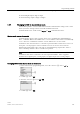
3.8 Configuring additional functions for LOGO!
LOGO!
102 Manual, 06/2014, A5E33039675
Viewing network connectors in LOGO!
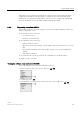
Consider a circuit program where a network digital input NI1 connects to the function block
B5. B5 is connected to Q4. To view this network input, follow these steps:
1. Switch LOGO! to programming mode.
2. Select "
①": Press or
3. Confirm"
①": Press
OK
4. Select "
②": Press or
5. Confirm "
②": Press
OK
(If required, enter your password and confirm with
OK
.)
6. Press
OK
in the circuit program window, and the cursor now appears as a solid square.
7. Move the cursor to the B5 block and then press
OK
. LOGO! shows the following display:
You can see that there is a network digital input NI1 connected at the first input of B5.
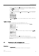
The following views are examples of network digital and analog outputs in LOGO!:
Available network input/output blocks in LOGO!Soft Comfort
The following network I/O blocks are available for you to create your circuit program in
LOGO!Soft Comfort:
● Network digital inputs: NI1 to NI64
● Network analog inputs: NAI1 to NAI32