
User Manual


LOGO! functions
4.1 Constants and connectors
LOGO!
Manual, 06/2014, A5E33039675
117
Outputs
●
Digital outputs
Digital outputs begin with the letter
Q
. The output numbers (Q1, Q2, ... Q20) correspond
with the numbers of the output connectors at the LOGO! Base Module and with those of
the expansion modules, in their order of installation.
LOGO! 0BA8 also provides 64 blank outputs and identifies them with the letter
x
. You
cannot reuse the blank outputs in a circuit program. The blank outputs differ from flags,
for example, which you can reuse. A blank output, for example, is useful for the special
function "Message texts" (Page 200), if only the message text is of significance to a circuit
program.
●
Analog outputs
Analog outputs begin with the letters
AQ
. Eight analog outputs are available, namely
AQ1, AQ2,... AQ8. You can only connect an analog output with the analog input of a
function, an analog flag AM or an analog output connector.
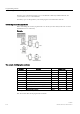
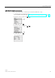
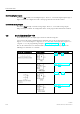
The following figure shows an example LOGO! configuration and the numbering of the
inputs and outputs for the circuit program.
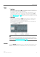
Note
LOGO! 0BA8 supports the graphical display of the analog value changes in the form of a
trend curve on the onboard display.
You can easily monitor each analog I/O in use by means
of the trend curves when LOGO! is in RUN mode. For more information on how to view the
trend curve, refer to "
Viewing the analog changes (Page 78)".
Flag blocks
The letters
M
or
AM
identify flag blocks. These are virtual outputs, which output the value of
their inputs. LOGO! 0BA8 provides 64 digital flags M1 to M64 and 64 analog flags AM1 to
AM64.