
User Manual


LOGO! functions
4.4 Special functions list - SF
LOGO!
Manual, 06/2014, A5E33039675
211
4.4.27
Shift register
Short description
You can use the shift register function to read the value of an input and to shift its bits left or
right. The output value corresponds with the configured shift register bit. The shifting
direction can be changed at a special input.
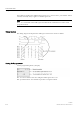
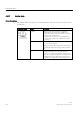
Symbol in LOGO!
Wiring
Description
Input In
Input read at the start of the function.
Input Trg A positive edge (0 to 1 transition) at input Trg
(Trigger) starts the special function. 1 to 0 transitions
are irrelevant.
Input Dir The signal at input Dir determines the shifting
direction for the shift register bits Sx.1 to Sx.8. "x"
refers to the configured shift register byte index 1, 2,
3, or 4.
Dir = 0: shift up
(Sx.1>>Sx.8)
Dir = 1: shift down
(Sx.8>>Sx.1)
Parameter Shift register bit that determines the value at output
Q.
Possible settings:
Byte index: 1 to 4
Q: S1 to S8
LOGO! provides a maximum of 32 shift register bits,
with eight bits per shift register.
Retentivity:
/ = no retentivity
R = the status is retentive.
Output Q The output value corresponds with the configured
shift register bit.
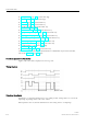
Functional description
The function reads the value at input In with a positive edge (0 to 1 transition) at input Trg
(Trigger).
This value is applied to shift register bit Sx.1 or Sx.8 depending on the shifting direction,
where "x" refers to the index number of the shift register and the number after the decimal
point refers to the bit number:
● Shift up: the value at input In is set at Sx.1; the previous value at Sx.1 is shifted to Sx.2;
the previous value at Sx.2 is shifted to Sx.3 etc.
● Shift down: the value at input In is set at Sx.8; the previous value at Sx.8 is shifted to
Sx.7; the previous value at Sx.7 is shifted to Sx.6 etc.
Output Q returns the value of the configured shift register bit.