
User Manual


Technical data
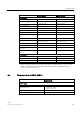
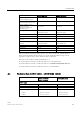
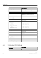
A.8 Technical data: LOGO! 12/24... LOGO! DM8 12/24R
LOGO!
Manual, 06/2014, A5E33039675
307
LOGO! 12/24RCEo
LOGO! 12/24RCE
LOGO! DM8 12/24R
Digital outputs
Number
4
4
Output type
Relay outputs
Relay outputs
Electrical isolation
Yes
Yes
In groups of
1
1
Control of a digital input
Yes
Yes
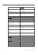
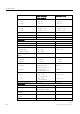
Continuous current I
th (per terminal)
Recommended range of
application ≥ 100 mA at
12 VAC/VDC
Max. 10 A per relay
Recommended range of
application ≥ 100 mA at
12 VAC/VDC
Max. 5 A per relay
Surge current
Max. 30 A
Max. 30 A
Incandescent lamp load (25000
switching cycles) at
1000 W 1000 W
Fluorescent tubes with ballast
(25000 switching cycles)
10 x 58 W 10 x 58 W
Fluorescent tubes,
conventionally compensated
(25000 switching cycles)
1 x 58 W 1 x 58 W
Fluorescent tubes,
uncompensated (25000
switching cycles)
10 x 58 W 10 x 58 W
Derating None; across the entire
temperature range
None; across the entire
temperature range
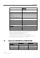
Short circuit-proof cos 1
Power protection B16, 600 A
Power protection B16, 600 A
Short circuit-proof cos 0.5 to 0.7
Power protection B16, 900 A
Power protection B16, 900 A
Parallel output circuits for power
increase
Not permitted Not permitted
Protection of output relay
(if desired)
Max. 16 A,
characteristic B16
Max. 16 A,
characteristic B16
Switching rate
Mechanical
10 Hz
10 Hz
Ohmic load/lamp load
2 Hz
2 Hz
Inductive load
0.5 Hz
0.5 Hz
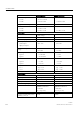
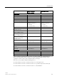
Notice: For fluorescent lamps with capacitors, you must consider the technical data of
fluorescent lamp ballasts. If the current exceeds the maximum allowed surge current,
appropriate contactor relays must switch the flourescent lamps.
The data was determined with the following devices:
● Siemens fluorescent tubes 58 W VVG 5LZ 583 3-1 uncompensated.
● Siemens fluorescent tubes 58 W VVG 5LZ 583 3-1 parallel compensated with 7 μF.
● Siemens fluorescent tubes 58 W VVG 5LZ 501 1-1N with ballast.