
User Manual


LOGO! installation and wiring
2.2 Installing/removing LOGO!
LOGO!
36 Manual, 06/2014, A5E33039675
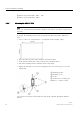
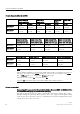
② LOGO! expansion modules, DM8 ..., AM...
③ LOGO! expansion modules, DM16 ...
2.2.3
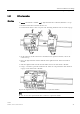
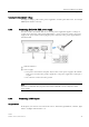
Mounting the LOGO! TDE
Note
Make sure you mount the LOGO! TDE vertically on a flat surface of an IP 65 or Type 4X/12
enclosure.
To prepare the mounting surface for the optional LOGO! TDE and mount it, follow these
steps:
1. Cut a 119 mm × 78.5 mm (tolerance: +0.5 mm) hole in the mounting surface.
2. Place the included gasket on the frontplate of the LOGO! TDE.
3. Fit the LOGO! TDE into the cutout you made in the mounting surface.
4. Attach the mounting brackets (included) to the LOGO! TDE.
5. Tighten the mounting screws on the mounting brackets to 0.2 Nm torque to secure the
LOGO! TDE.
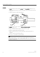
①
Mounting brackets
②
Mounting screws
③
Gasket
④
Cabinet door or control panel
(Thickness: 1.5
mm to 4 mm)
You can then connect the LOGO! TDE to the LOGO! Base Module through the Ethernet
interface.