
User Manual


LOGO! installation and wiring
2.3 Wiring LOGO!
LOGO!
42 Manual, 06/2014, A5E33039675
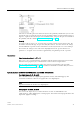
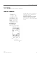
The inputs I1, I2, I7 and I8 provide digital inputs, and the inputs AI3, AI4, AI1 and AI2 provide
analog inputs, as described in the topic "Constants and connectors (Page 115)". AI3
corresponds to the input terminal I1; AI4 corresponds to I2; AI1 corresponds to I7; AI2
corresponds to I8. The use of AI3 and AI4 is optional. You configure your LOGO! to use
either two or four analog inputs as the topic "Setting the number of AIs in LOGO!
(Page 266)" describes.
When using inputs I1, I2, I7 and I8 as analog inputs, only the range from 0 to 10 VDC is
available.
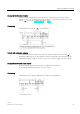
Connecting a potentiometer to inputs I1, I2, I7 and I8
To allow you to achieve 10 V as the maximum value when you completely turn the
potentiometer once, you must connect a series resistor on the potentiometer's input side
regardless of the input voltage (see figure below).
We suggest the following sizes of potentiometers and associated series resistors:
Voltage
Potentiometer
Series Resistor
12 V
5 kΩ
-
24 V
5 kΩ
6.6 kΩ
When using a potentiometer and 10 V input voltage as the maximum value, you must ensure
that with a connected input voltage of 24 V, 14 V must release via the series resistor to
ensure a maximum supply of 10 V when you turn the potentiometer one full rotation. With a
voltage of 12 V, you can neglected this.
Note
The LOGO! AM2 expansion module provides additional analog inputs. The LOGO! AM2
RTD expansion module provides PT100/PT1000 inputs.
Always use twisted and shielded cables fo
r analog signals, and keep these as short as
possible.