
User Manual


LOGO! installation and wiring
2.3 Wiring LOGO!
LOGO!
Manual, 06/2014, A5E33039675
43
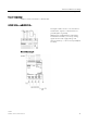
Sensor connections
Connect sensors to LOGO! as shown below.
LOGO! 12/24.... and LOGO! 24...
The inputs of these devices are not isolated
and therefore require a common reference
potential (chassis ground).
With LO
GO! 12/24RCE/RCEo and LOGO!
24CE/24CEo modules, you can tap analog
signals between the supply voltage and
chassis ground (* = series resistor (6.6 k
Ω) at
24 VDC).
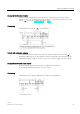
Connection example