
User Manual


LOGO! installation and wiring
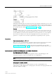
2.3 Wiring LOGO!
LOGO!
Manual, 06/2014, A5E33039675
45
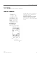
LOGO! AM2
①
FE terminal for connecting earth and
shielding the analog measuring cable
③
Cable shielding
②
Earth
④
Standard DIN rail
The illustration above shows an example of four-wire current measurement and two-wire
voltage measurement.
Connecting a two-wire sensor to the LOGO! AM2
Wire up the two-wire sensor's connecting wires as follows:
1. Connect the sensor's output to connection U (0 V to 10 V voltage measurement) or to
connection I (0/4 mA to 20 mA current measurement) of the AM2 module.
2. Connect the plus connector on the sensor to the 24 V supply voltage (L+).
3. Connect the ground connection of the current output M (on the right side of the sensor, as
shown in the figure above) to the corresponding M input (M1 or M2) on the AM2 module.
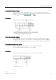
LOGO! AM2 RTD
You can connect a maximum of two PT100 sensors or two PT1000 or one PT100 plus one
PT1000 sensor in a two-wire or three-wire connection or in a mixed use of two-wire and
three-wire connection to the module. Note that the sensor type supported by the module is
only PT100 or PT1000 with the default temperature coefficient of α= 0.003850.
For a
two-wire
connection, you need to short-circuit terminals U1- and IC1 or U2- and IC2.
Errors caused by the ohmic resistance of the measuring line are not compensated for this
type of connection. If a PT100 sensor is connected, a line resistance of 1 Ω is proportional to
measuring error of +2.5 °C; if a PT1000 sensor is connected, a line resistance of 1 Ω is
proportional to measuring error of +0.25 °C.
A
three-wire
technique suppresses the influence of the cable length (ohmic resistance) on
the result of the measurement.