
User Manual


LOGO! installation and wiring
2.4 Putting into operation
LOGO!
52 Manual, 06/2014, A5E33039675
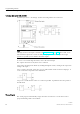
STOP
RUN
Action of LOGO!:
• The input data is not read.
• The circuit program is not executed.
• The relay contacts are permanently open
or the solid-state outputs are switched off.
Action of LOGO!:
• LOGO! reads the status of the inputs.
• LOGO! uses the circuit program to calculate the
status of the outputs.
• LOGO! switches the relay/solid-state outputs on
or off.
Note
After switching the power on, the system briefly switches through the outputs on the LOGO!
24CE/24CEo. With an open circuit, a voltage of > 8 V can occur for up to approximately 100
ms; wh
en the circuit is loaded, this time reduces to a matter of microseconds.
LOGO! expansion modules, operating states
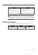
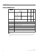
LOGO! expansion modules have three operating states. The color of the LED (RUN/STOP)
indicates one of three operating states for LOGO! expansion modules.
Green (RUN)
Red (STOP)
Orange/Yellow
The expansion module
communicates with the device
to the left.
The expansion module does
not
communicate with the device to
its left.
Initialization phase of the
expansion module