
User Manual


Programming LOGO!
3.3 From circuit diagram to LOGO! program
LOGO!
60 Manual, 06/2014, A5E33039675
Creating this circuit with LOGO!
In LOGO! you create a circuit logic by interconnecting blocks and connectors:
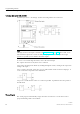
Note
A
lthough you have four inputs available for logic operations (Page 120), most of the views
only show three inputs for reasons of clarity. You progr
am this fourth input and assign
parameters just like you do with the other three inputs.
To create a new circuit logic in LOGO!, start at the circuit output.
The output is the load or relay that is to be switched.
Convert the circuit logic into blocks by working through the circuit, starting at the output and
ending at the input:
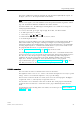
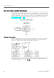
Step 1: Connect the make contact S3 in series with another circuit element to output Q1. A
series connection corrsponds to the AND block:
Step 2: Use an OR block to connect S1 and S2 in parallel. A parallel circuit corresponds to
the OR block:
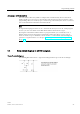
Unused inputs
The circuit program automatically assigns the unused connectors a status that ensures
proper functioning of the relevant block.