
User Manual


Programming LOGO!
3.4 The four golden rules for operating LOGO!
LOGO!
Manual, 06/2014, A5E33039675
61
In our example we shall use only two inputs of the OR block and two inputs of the AND
block; the third and fourth inputs are unused.
Now connect the I/O to LOGO! .
Wiring
Connect the switches S1 to S3 to the screw terminals of your LOGO! :
● S1 to connector I1 of LOGO!
● S2 to connector I2 of LOGO!
● S3 to connector I3 of LOGO!
The output of the AND block controls the relay at output Q1. The load E1 connects to output
Q1.
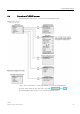
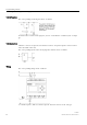
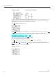
Wiring example
The following figure shows you the wiring, based on a 230 VAC version of LOGO!.
3.4
The four golden rules for operating LOGO!
Rule 1: Changing the operating mode
● You create the circuit program in programming mode. After power is on, and when the
program is empty in LOGO!, LOGO! selects the programming mode by default.
● You can edit timer and parameter values of an existing circuit program in both
parameter
assignment mode
and
programming mode
. During
parameter assignment
LOGO! is in