
User Manual


Programming LOGO!
3.7 Writing and starting the circuit program
LOGO!
68 Manual, 06/2014, A5E33039675
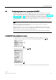
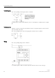
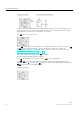
Circuit diagram
The corresponding circuit diagram shows as follows:
Translated into a LOGO! circuit program, you use an OR block to control relay K1 at output
Q1.
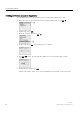
Circuit program
Switch S1 connects to input I1 and switch S2 connects to input I2. Inputs I1 and I2 connect
to the OR block connectors.
The corresponding layout of the circuit program in LOGO! shows as follows:
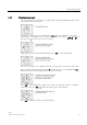
Wiring
The corresponding wiring shows as follows:
S1 switches input I1, while S2 switches input I2. The load connects to the relay Q1.